Advanced Tutorial: Check FAA Requirements
In this tutorial you will evaluate a beam for compliance with FAA Position and Anti Collision strobe lighting requirements.
If you need to review the basics of Photopia for SOLIDWORKS, then start with the SOLIDWORKS Beginner Tutorial.
Skill Level
Intermediate
Downloads
none
1. Open your project
Open SOLIDWORKS and open an assembly you would like to analyze.
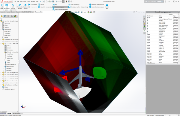
Add the appropriate light source and assign appearances to the optical parts.
2. Setup Coordinates
Set a Photometric Origin
Add a Reference Point at the exit surface of your optic by going to Insert > Reference Geometry > Point.
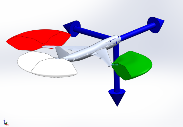
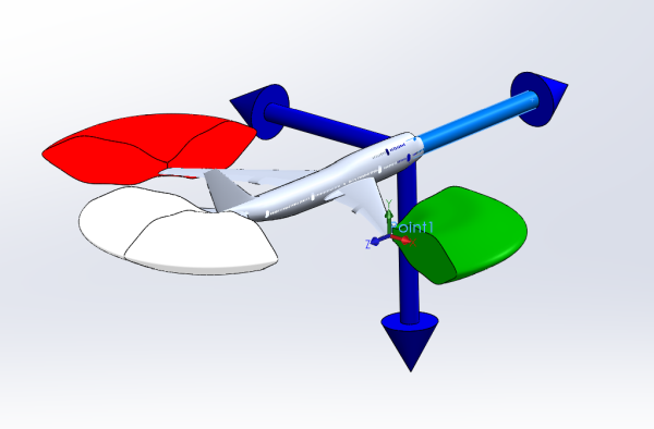
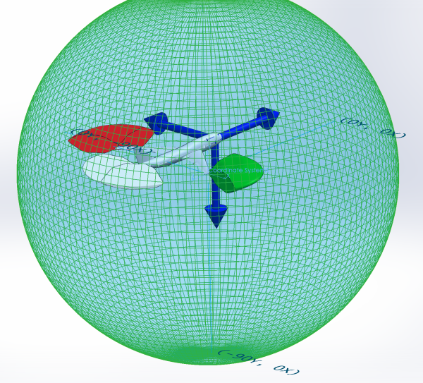
Setup Reference Coordinate System
Add a Reference Coordinate System by going to Insert > Reference Geometry > Coordinate System.
For the origin select the point you defined in Step 3.
The +Z axis should point towards the aft of the aircraft.
The +Y axis should point up with respect to gravity.
Click OK to add the coordinate system.
3. Photometric Settings
Select the new coordinate system defined in Step 4.
Select Photometric Settings in the Photopia CommandManager.
Change the Photometry Type to Aerospace/Automotive.
Ensure the Photometric Type is Type A.
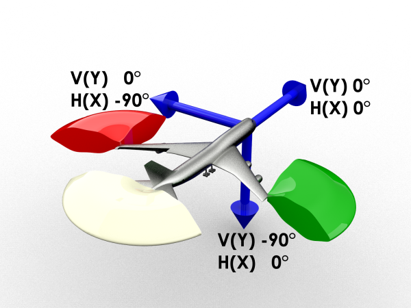
Set the Horizontal angles from -180 to 180 in 5 degree increments [-180(5)180].
Set the Vertical angles from -90 to 90 in 5 degree increments [-90(5)90].
As long as your Reference Coordinate System was oriented properly, your Photometric Coordinates should match the images below.
Click OK to save the Photometric Settings.
4. Raytrace Settings
Select Raytrace Settings in the Photopia CommandManager.
Keep the default of 2.5M rays and 25 ray reactions.
Ensure the Photometric Type is Type A.
Click OK to save the Raytrace Settings.
Run the raytrace.
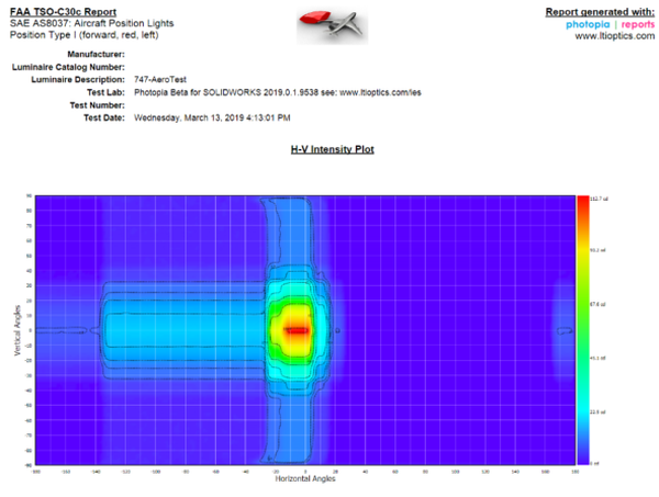
6. View FAA Reports in SOLIDWORKS
Select Results in the Photopia CommandManager.
In the Results window, choose the Photometric Report section and find the Aero-.... reports in the drop down.
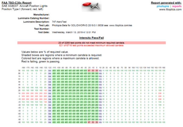
7. View in Photopia Reports
Select Results in the Photopia CommandManager.
In the Results window, choose the IES File section and then click on the export button in the upper right to save the IES file to disk.
Open photopia|reports and browse to the IES file, or right click on the exported IES file and choose Open.
Choose IES Report from the left menu and then choose any of the 4 FAA Compliance Reports from the thumbnails.