Intermediate Tutorial: Design a Convex Lens
We will develop a standard convex lens, also known as biconvex or double convex. The goal is to collimate the Lambertian distribution from a typical discrete LED into a narrow beam. Convex lenses are useful in applications where you need to achieve a very controlled, narrow beam with a crisp edge. Typical applications include flashlights/headlamps, theatrical spotlights, and imaging optics. Tradeoffs in these style designs can be seen with lower efficiency since the lens only controls a portion of the original distribution from the source, and a non-uniform thickness.
If you need to review the basics of Photopia for SOLIDWORKS, then start with the SOLIDWORKS Beginner Tutorial.
Skill Level
Intermediate
Downloads
none

1. Initial Assembly Setup
Open SOLIDWORKS and start a new Assembly document.
Set the units as Metric (MMGS).
Save the assembly as “Convex Lens”.
From the Photopia CommandManager tab, click “Add Lamp”.
Click on “Browse Lamps”.
In the “Choose a Lamp” menu type “XHP” into the search bar, this will show all the lamps with “XHP” in the name.
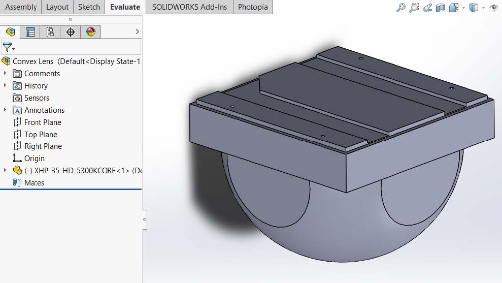
Double click on the “Cree XHP-35-HD-5300KCORE” lamp designation.
OK ( ✔ ) to insert the lamp at the assembly origin.
Save the assembly
Create a PCB part
Go to File > New, and select a new part documents
Make your part units in Metric (MMGS).
Save the part as “PCB”.
Begin a new sketch on the Top Plane,
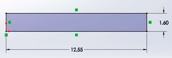
sketch the following rectangle to represent the half cross section of the PCB which we will revolve to make a solid part:
Click on the Features CommandManager and select Revolved Boss/Base
revolve the sketch to create a solid part
Save the Part
Place the PCB Part
Go back to your Convex Lens assembly
Click on the Assembly CommandManager and select Insert Component.
Select the PCB part you just created and click OK ( ✔ ) to insert the part into the assembly.
Right click on the PCB and change the part from “Fix” to “Float”.
Mate the PCB to the back of the solder pads of the XHP-35:
In order to make sure the LED is centered on the PCB, mate the PCB front plane to the assembly front plane. Also mate the PCB right plane to the assembly right plane:
Save the assembly
Create a Simple Housing Part
Go to File > New, and select a new part documents
Make your part units in Metric (MMGS).
Save the part as "Housing".
Begin a new sketch on the Top Plane,
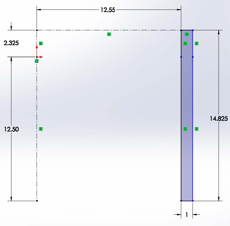
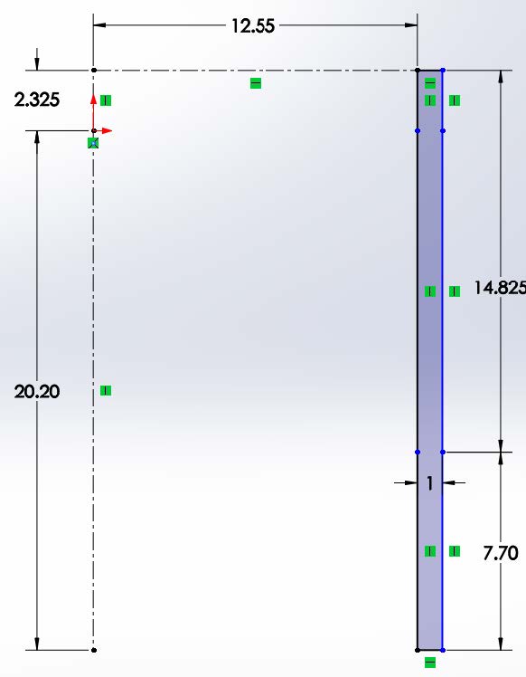
sketch the following rectangle to represent the half cross section of the Housing which we will revolve to make a solid part
The sketch adds two centerlines, the first goes up and 2.325mm long, this is the distance from the lamp center to the back of the PCB. The second goes down and is 12.5mm long, this is the distance from the lamp center to our lens center (which we will design later on)
Click on the Features CommandManager and select Revolved Boss/Base
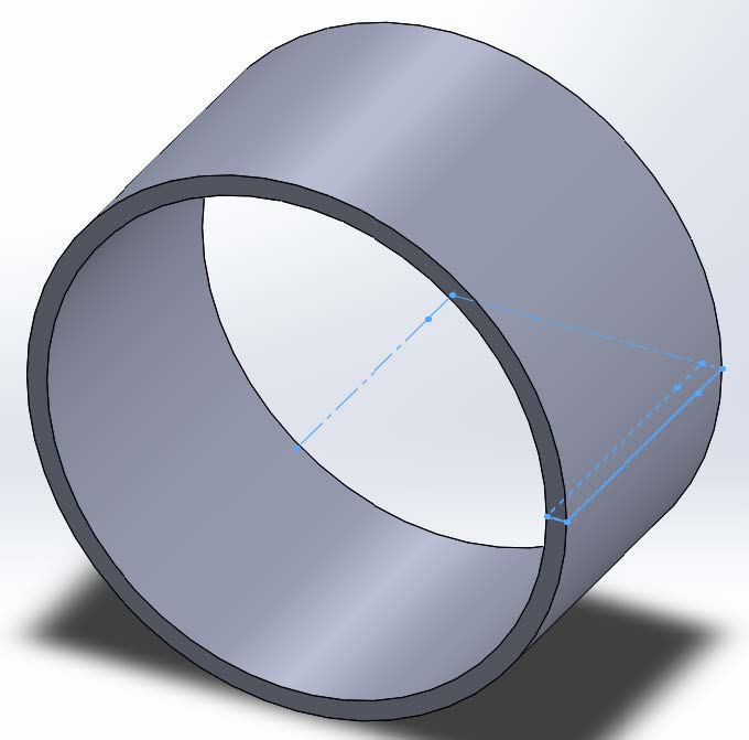
revolve the sketch to create a solid part
Save the Part
Place the Housing Part
Go back to your Convex Lens assembly
Click on the Assembly CommandManager and select Insert Component.
Select the Housing part you just created and click OK ( ✔ ) to insert the part into the assembly.
Right click on the Housing and change the part from “Fix” to “Float”.
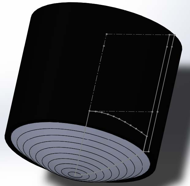
In the FeatureManager Design Tree, expand the Housing part, expand the Revolve feature, right click on the sketch and select “Show”.
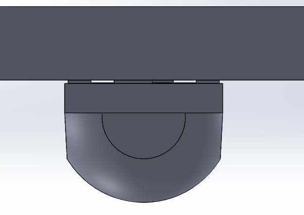
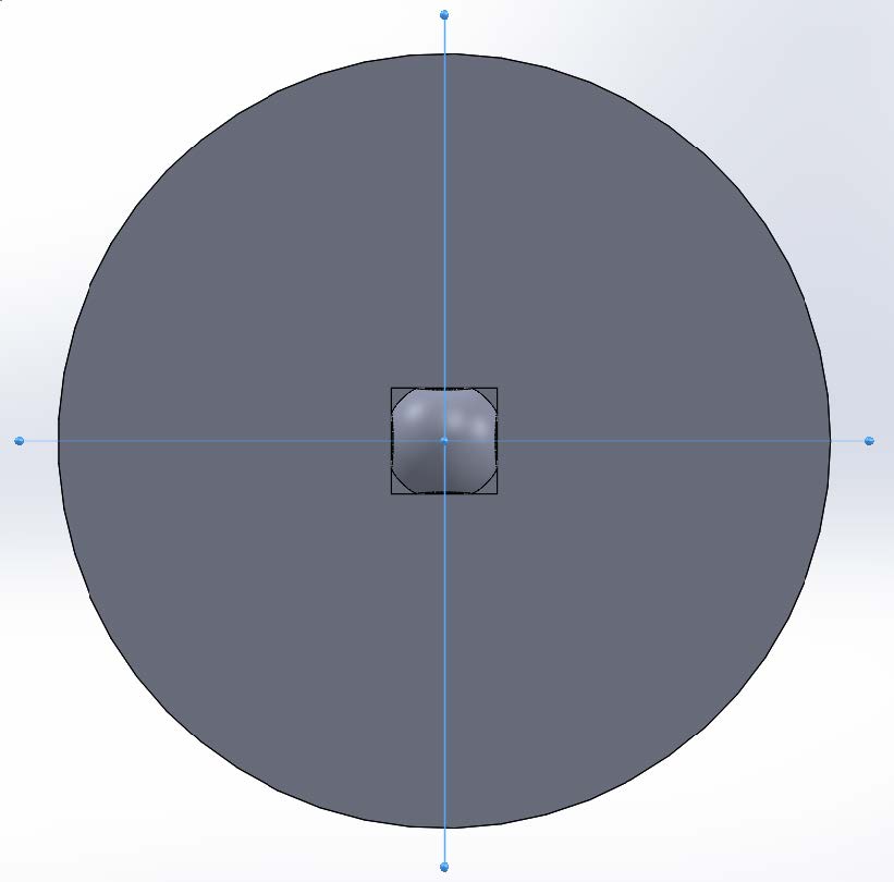
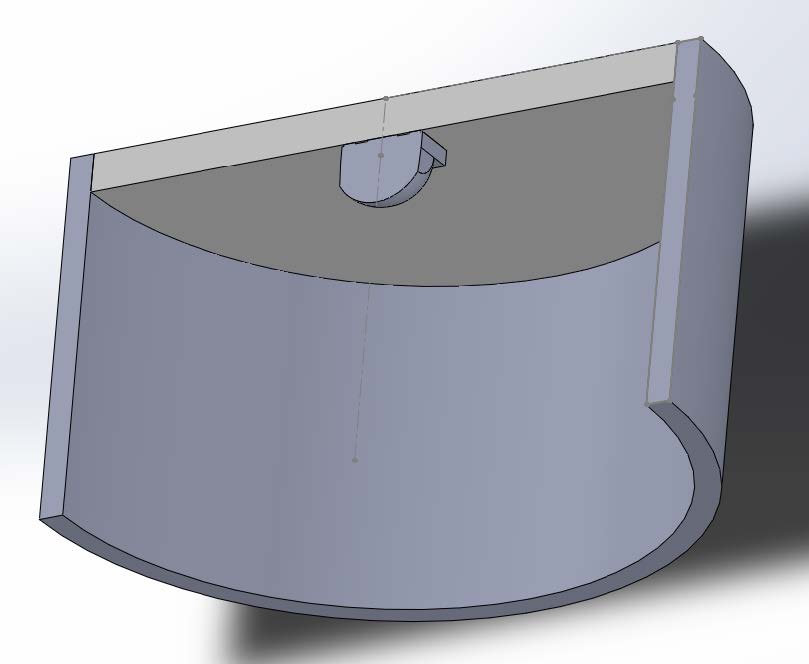
The cylindrical housing is upside-down relative to our assembly so we need to mate the top flat edge of the Housing cylinder to the back face of the PCB. Then we need to mate the inside cylinder of the housing to the outside cylinder of the PCB. Last, mate the top plane of the housing to the top plane of the assembly. The top plane cross section of the assembly will look like this
Save the assembly
2. Assign Photopia Materials
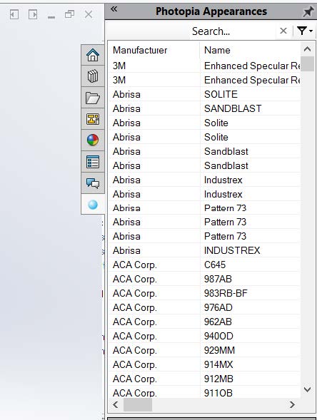
Click on the Photopia Appearance Task Pane Tab
In the search bar type “PCB”, select the reflective material listed as Generic White PCB at 76% reflectance. Drag the material name onto the PCB part in the model and assign it to the part level.
In the search bar type “black”, select the reflective material listed as Flat Black at 4% reflectance. Drag the material name onto the Housing part in the model and assign it to the part level.
Save the assembly.
3. Photometric Settings
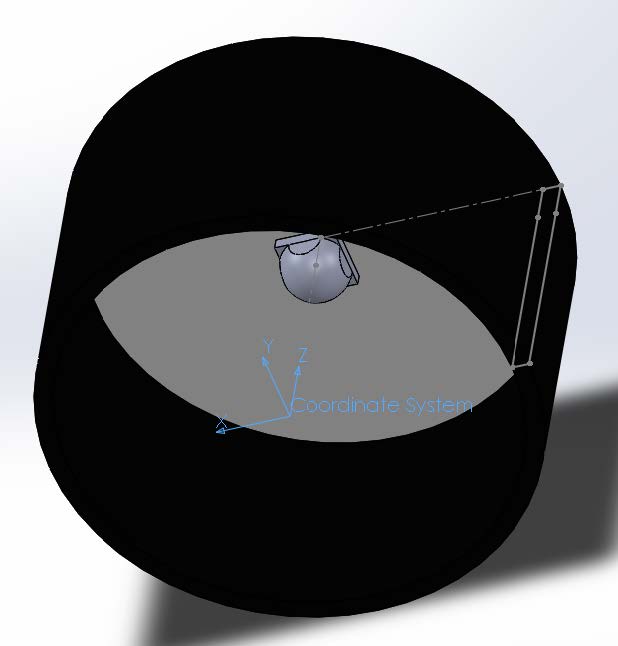
Add a reference coordinate system by going to Insert > Reference Geometry > Coordinate System.
For the origin select the point at the end of the centerline sketch for the housing.
The Z axis is defined by the same centerline with +Z pointing behind the LED since 0° vertical (nadir) is along the -Z axis, which is where our convex lens will be aimed towards. Click OK ( ✔ ) to add the coordinate system.
Select the new coordinate system and under the Photopia CommandManager select Photometric Settings.
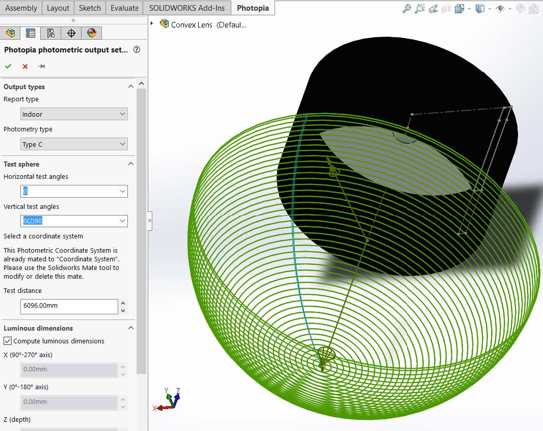
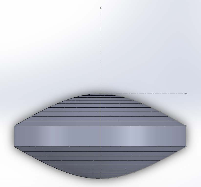
Since this is an axially symmetric beam, the horizontal angle set will be only 0°.
Since we are trying to develop a very narrow beam we expect our intensities to rapidly change over the vertical angle set, so we will increase our resolution to better capture that change. For the vertical angles choose 0(2)90 where our starting angle is 2°, our ending angle is 90° (no up light), and our increment is 2°:
Click OK ( ✔ ) to save the Photometric Settings.
4. Raytrace Settings
Click on the Photopia CommandManager and select Raytrace Settings.
We will keep all of the default settings except we will change the Sample Ray Count from 0 to 250 so we can see a sample set of the 3D rays.
Click OK ( ✔ ) to save the Raytrace Settings.
Save the assembly.
Click on the Photopia CommandManager and select Run Raytrace so we can see the distribution from the bare LED and simple housing.
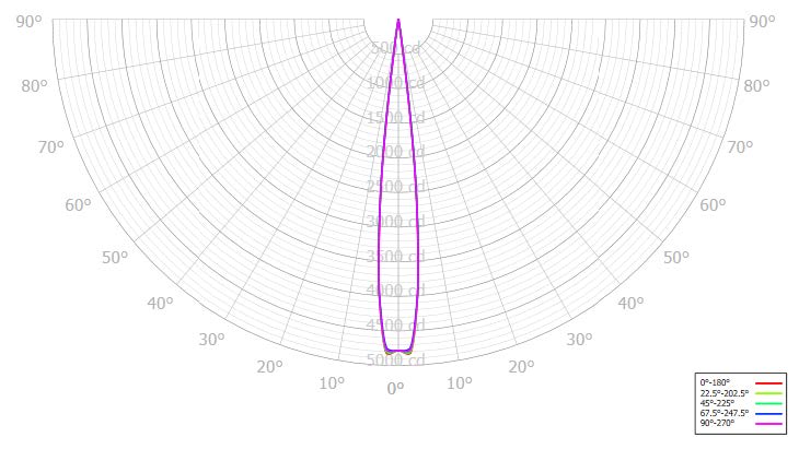
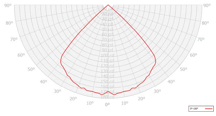
When the raytrace is complete select Results and view the Raytrace Report. Note that the optical efficiency is ~50.6% with the majority of the light being absorbed by the flat black housing. The beam angle (full width half max) is ~90.3° and the candela polar plot will look like this:
Save the assembly.
5. Design Convex Lens
Define Lens Profile
Go to File > New, and select a new part documents
Make your part units in Metric (MMGS).
Save the part as "Convex Lens".
Begin a new sketch on the Top Plane,
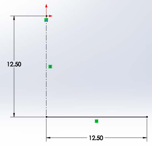
Draw a centerline from the origin straight down. Make the centerline 12.5mm long. The centerline will define our lamp center, and our 0° aiming direction.
Draw a line from the origin straight to the right. Make the line 12.5mm long (so the lens will be 25mm in diameter). This line will serve as our base profile to create the revolved Convex lens.
Create PODT Lens
Click on the Photopia CommandManager and select “Design Lens”.
The Lamp Center is the origin at the top of the centerline.
The base profile is the horizontal line.
We will keep the default number of Prism Steps at 10
We will keep the default Index of Refraction at 1.491 for generic acrylic.
Additionally we will keep the default Minimum Thickness at 3.00mm.
The edge to define the 0° aiming angle is the centerline.
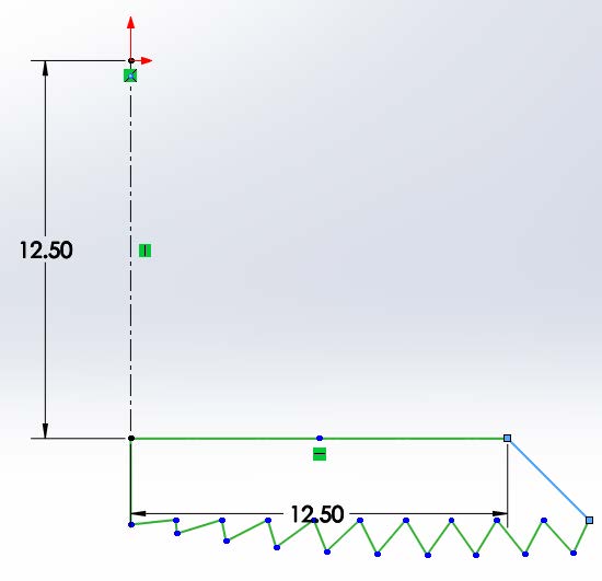
Last, our goal is to create as narrow a beam as possible, so we will adjust the aiming string to be “0(5)0” which means that the lens is aimed at 0° at the start of the profile, 0° at the end of the profile, and changes in 5° increments (which does not matter here since we have the same aiming angle at the start and the end). Click OK ( ✔ ) to complete the lens design:
NOTE - the default profile created by the Parametric Optical Design Tools is a prismatic style lens (Fresnel), we will change this to be a smooth lens profile in the next few steps. 24.
Revolve Lens
Click on the Features CommandManager and select “Revolved Boss/Base”.
The Axis of Revolution is the centerline and we will use Blind and 360° Direction1 settings
Click OK ( ✔ ) to complete the revolved feature and close the sketch.
Update Lens
In the FeatureManager Design Tree select the “Revolve1” feature.
Click on the Photopia CommandManager and select “Design Lens”.
Under “Reload” select the PODT Refractor that you designed, and Click OK ( ✔ ) to connect that design profile to the revolve feature, allowing you to adjust the profile in the future without recreating the feature.
We will now change the lens from a Fresnel style lens to a smooth, convex, lens.
Select the “Revolve1” feature, go to Photopia > Design Lens, and click “Open the PODT Window”.
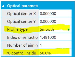
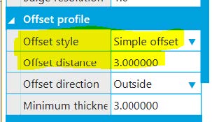
Under Optical Parameters change the profile type to be “Smooth” and change the % Control Inside to be “50” (this will make the lens style biconvenx or double convex rather than plano convex).
Also, under Offset Profile change the Offset style to be “Simple offset”, and change the Offset distance to be 3mm.
Exit out of the PODT window and click OK ( ✔ ) to update your lens profile and solid.
Save your part.
6. Assemble Components
Go back to your Convex Lens assembly.
Click on the Assembly CommandManager, select “Insert Component”, select the Convex Lens part and click OK ( ✔ ) to add it to your assembly.
As you will see the lens will be added to the model but behind the lamp and facing the opposite direction. We must flip the lens around.
Right click on the lens and change the property from “fix” to “float”.
Select the lens and under the Assembly CommandManager, select Rotate Component (an option under Move Component). Chose by delta XYZ for the rotate option and 180° in the Y axis. Click OK ( ✔ ) to commit the rotate.
Mate the lamp origin to the lamp center of the lens sketch.
Temporarily hide the housing so we can view just the lens and LED.
Under the FeatureManager Design Tree, expand the Fresnel Lens part, right click on the sketch and select the option to show the sketch.
Click on mate. Your first point will be the lamp center point from the part sketch. The second point will be the origin from the CXB-1830 lamp part. This will move the lens slightly forward relative to the lamp.
Save the assembly
Adjust the Housing
Change the display style for the Housing to Show from Hide.
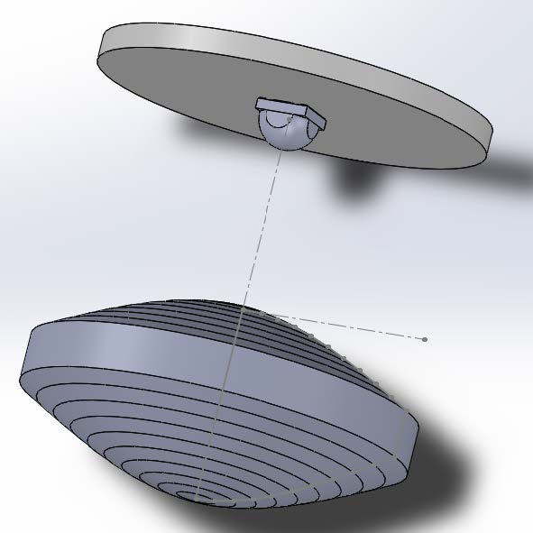
Notice how there is a gap between the end of the cylindrical housing and the edge of the lens, we must extend the housing to close off the assembly.
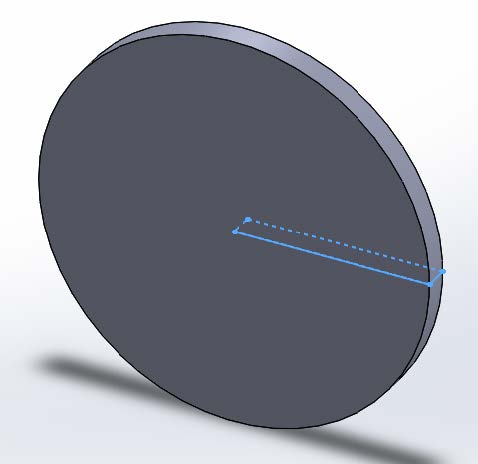
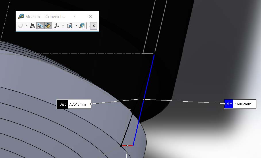
Measure the distance from the end of the housing to the bottom edge of the lens cylinder, the distance is 7.68mm:
Open the Housing part.
Edit the original sketch so that the centerline increases in length by 7.7mm (from 12.5 to 20.2). Add new line segments on the cylinder to add the additional 7.7mm in housing height (delete the original bottom horizontal line to close the rectangle):
Exit the sketch
Save the part
Close the part and rebuild the assembly
7. Run Raytrace
Assign the refractive Generic Clear Acrylic material to the lens part.
Save the assembly
Run the raytrace
View the results
A beam angle (full width half max) of 11.9° has been achieved, narrowing the beam significantly from the 120° lambertian beam emitted from the XHP.