Advanced Tutorial: Design a TIR Collimator
We will develop a typical TIR (total internal reflection) collimator lens with the goal of creating a narrow beam of light from an LED. TIR collimators are useful in that you can achieve a narrow beam while controlling the entire initial distribution from the source. Other optic types, such as a parabolic reflector, will only control the light that is incident on the optic, ignoring the portion of the beam that passes that doesn’t interact.
If you need to review the basics of Photopia for SOLIDWORKS, then start with the SOLIDWORKS Beginner Tutorial.
Skill Level
Intermediate
Downloads
none
1. Add a Lamp
Open SOLIDWORKS and start a new Assembly document.
Make your assembly units in Metric (MMGS).
Save the assembly as “TIR Collimator Lens”.
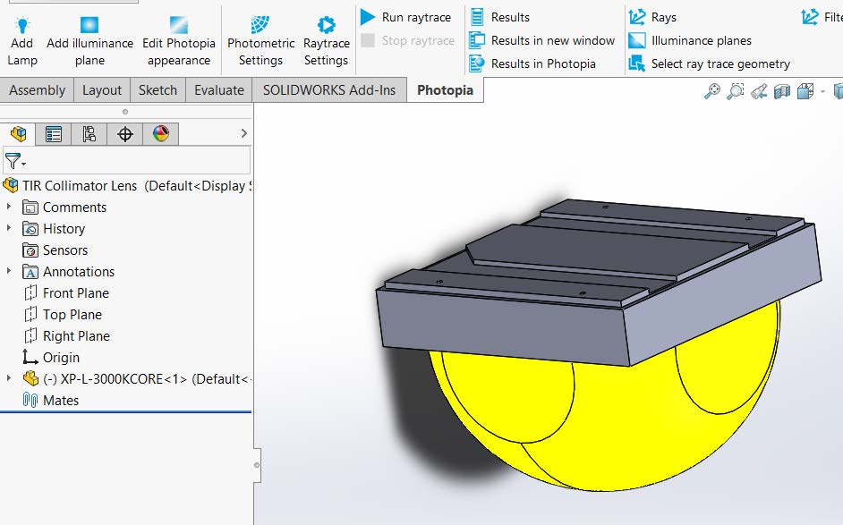
From the Photopia CommandManager, click “Add Lamp”.
Click on “Browse Lamps”.
In the “Choose a Lamp” menu type “XP-L” into the search bar, this will show all the lamps with “XP-L” in the name.
Double click on the “Cree XP-L-3000KCORE” lamp designation.
Click OK ( ✔ ) to insert the lamp at the assembly origin.
Save the Assembly
2. Design Outer TIR Surface
Outer TIR Boundary
Go to File > New, and select a new part document.
Make your part units in Metric (MMGS).
Save the part as “TIR Collimator Lens”.
Begin a new sketch on the Top Plane.
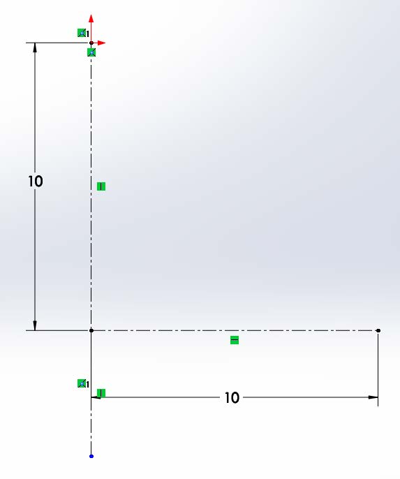
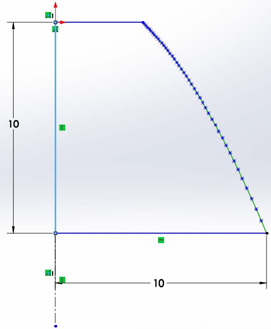
Draw a centerline from the origin straight down. Make the line 10mm long. The centerline will define our lamp center and our 0° aiming direction.
Draw a centerline from the end of the vertical centerline straight to the right. Make the centerline 10mm long (so the TIR portion of the lens will be 20mm in diameter). This right point of this centerline will define our starting point for the TIR profile. Also draw a second vertical centerline below the first which will be our Revolve feature axis (and is crucial for SOLIDWORKS and the ability to alter the design profile.
PODT Reflector
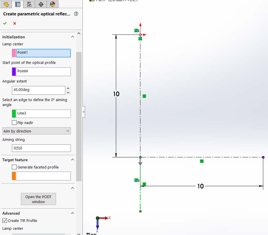
Click on the Photopia CommandManager and select “Design Reflector”. Note that while we are creating a refractive lens part, we will use the reflector design tool to generate the TIR profile, where based on the incidence angle of the light onto the TIR surface, the light will internally reflect towards 0° rather than refracting out of the lens. It does not matter that this lens feature is designed using a reflector tool since we will give it a refractive lens material later on.
The Lamp Center is the origin at the top of the centerline.
The start point of the reflector is the point at the right end of the horizontal centerline.
The angular extend is 45° (positive, going counter-clockwise) since the start point is 10mm down and 10mm right from the lamp center.
The edge to define the 0° aiming angle is the lower vertical centerline.
Our goal is to create as narrow a beam as possible, so we will adjust the aiming string to be “0(5)0” which means that the lens is aimed at 0° at the start of the profile, 0° at the end of the profile, and changes in 5° increments (which does not matter here since we have the same aiming angle at the start and the end).
Under the Advanced section, check the “Create TIR Profile” option, this will close off the reflector profile so a solid revolved feature can be made.
Click OK ( ✔ ) to complete the TIR profile design.
Revolve TIR Surface
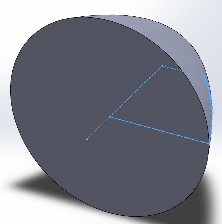
Click on the Features CommandManager and select “Revolved Boss/Base”.
The Axis of Revolution is the lower centerline and we will use Blind and 360° Direction1 settings.
Click OK ( ✔ ) to complete the revolved feature and close the sketch:
Associate Revolve1 with PODT
In the FeatureManager Design Tree select the “Revolve1” feature.
Click on the Photopia CommandManager and select “Design Reflector”.
Under “Reload” select the PODT Reflector that you designed, and Click OK ( ✔ ) to connect that design profile to the revolve feature, allowing you to adjust the profile in the future without recreating the feature.
Save the part
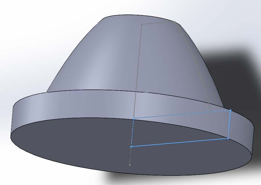
Design the Flange
Under the Revolve feature of the TIR, right click on the sketch and change the display to be “Show”.
Create a new sketch on the top plane.
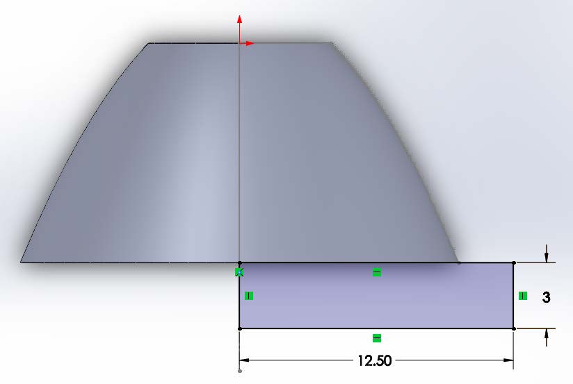
Draw a corner rectangle with the first corner being the center point of the bottom of the TIR sketch. The opposite corner will be to the right and below of the lower, start, point of the TIR curve. The final sketch should look like this:
Click on the Features CommandManager and select “Revolved Boss/Base”. The Axis of Revolution is the original centerline and we will use Blind and 360° Direction1 settings. Click OK ( ✔ ) to complete the revolved feature and close the sketch:
Save the part
3. Design Central Dome and Shaft
Design Input Dome and Central Shaft
Under the Revolve feature of the Flange, right click on the sketch and change the display to be “Show”.
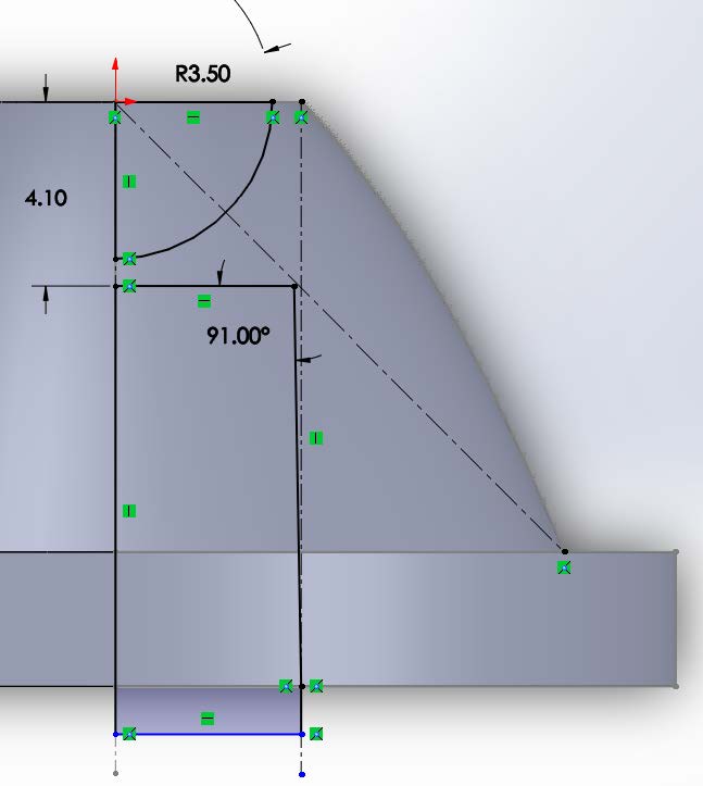
Start a new sketch on the top plane.
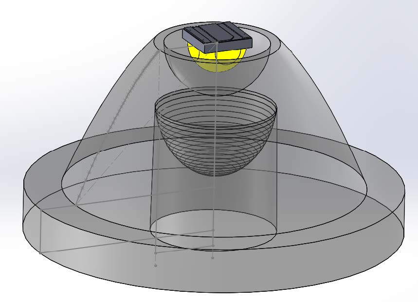
Draw the hemispherical input dome using a centerpoint arc, the centerpoint is the lamp center and the radius will be 3.5mm with an extent of 90°. Close the arc with vertical and horizontal lines.
Draw two construction lines, the first in a vertical line going from the top of the TIR design profile straight down. The second goes from the lamp center to the bottom corner of the TIR design profile. This will show the light that is incident on the TIR and will be aimed straight down towards 0°. We do not want to interfere with this light that we are already controlling with the TIR profile.
Draft the central shaft sketch with a 1deg draft. The shaft will create a cylinder that has the depth equal to where the two construction lines intersect. It will have the end radius no greater than where the radius of the top of the TIR. The sketch should slightly extend beyond the flange in order to create a clean cut.
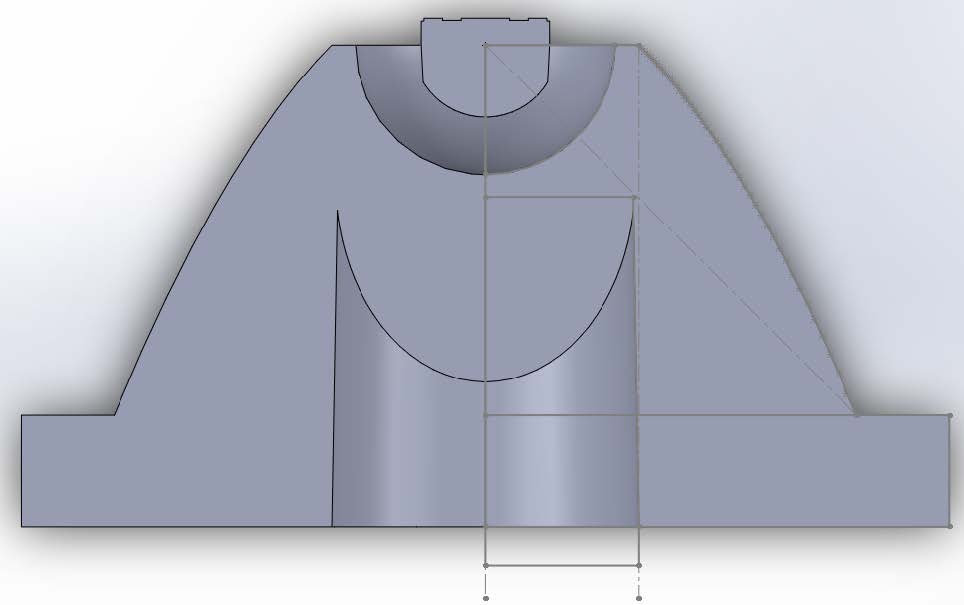
The sketch of these steps should look like this:
Click on the Features CommandManager and select “Revolved Cut”. The Axis of Revolution is the original centerline and we will use Blind and 360° Direction1 settings. Click OK ( ✔ ) to complete the cut and close the sketch:
Save the part
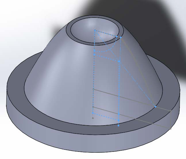
Design the Central Convex Feature
Under the Revolve feature of the Cut, right click on the sketch and change the display to be “Show”.
Start a new sketch on the top plane.
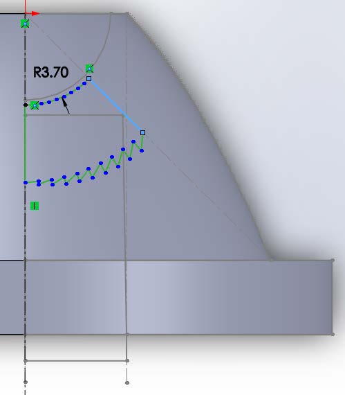
Create a centerline starting at the lamp center and going straight down. This will define the lamp center point and the 0° aiming angle.
Draw a centerpoint arc with the center at the lamp center, the start point below the lamp (along the centerline and slightly larger than the input dome. Make the radius 3.7mm and the angular extent 45°.
Click on the Photopia CommandManager and select “Design Lens”.
The Lamp Center is the origin at the top of the centerline.
The base profile is the 45° arc.
We will keep the number of Prism Steps at 10.
We will keep the default Index of Refraction at 1.491 for generic acrylic.
Additionally we will keep the default Minimum Thickness at 3.00mm.
The edge to define the 0° aiming angle is the centerline.
Last, our goal is to create as narrow a beam as possible, so we will adjust the aiming string to be “0(5)0” which means that the lens is aimed at 0° at the start of the profile, 0° at the end of the profile, and changes in 5° increments (which does not matter here since we have the same aiming angle at the start and the end). Click OK ( ✔ ) to complete the lens design.
Update Central Convex Feature
Click on the Features CommandManager and select “Revolved Boss/Base”.
The Axis of Revolution is the centerline and we will use Blind and 360° Direction1 settings.
Click OK ( ✔ ) to complete the revolved feature and close the sketch.
In the FeatureManager Design Tree select the latest Revolve feature.
Click on the Photopia CommandManager and select “Design Lens”.
Under “Reload” select the PODT Refractor that you designed, and Click OK ( ✔ ) to connect that design profile to the revolve feature, allowing you to adjust the profile in the future without recreating the feature.
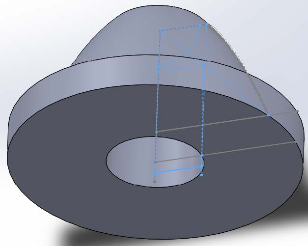
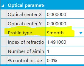
We will now change the lens from a Fresnel style lens to a smooth, convex, lens. Select the latest Revolve feature, go to Photopia > Design Lens, and click “Open the PODT Window”. Under Optical Parameters change the profile type to be “Smooth”.
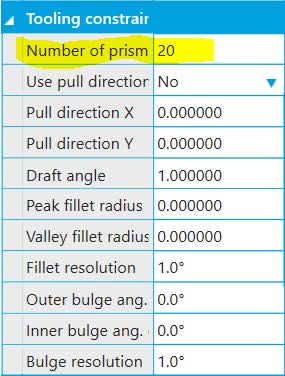
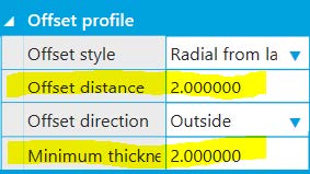
Also, under Tooling Constraints change the number of prism steps to be “20” to create a smoother profile. Last, under Offset profile change the offset distance and minimum thickness to 2mm to pull the convex lens feature in closer to the base arc profile. Exit out of the PODT window and click OK ( ✔ ) to update your lens profile.
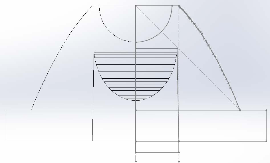
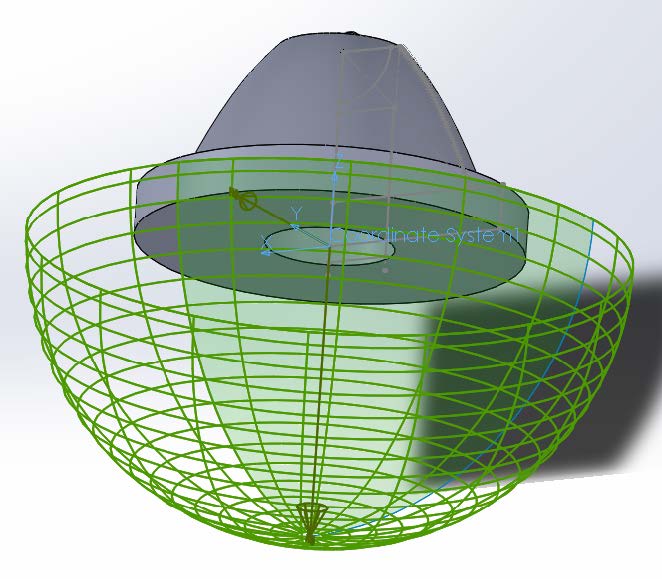
The top view, wireframe, of your lens will look like this
Save the completed lens part
4. Complete Assembly
Go back to your TIR Collimator assembly.
Click on the Assembly CommandManager, select “Insert Component”, select the Fresnel Lens part and click OK ( ✔ ) to add it to your assembly.
As you will see the lens will be added to the model but behind the lamp and facing the opposite direction. We must flip the lens around.
Right click on the lens and change the property from “fix” to “float”.
Select the lens and under the Assembly CommandManager, select Rotate Component (an option under Move Component). Chose by delta XYZ for the rotate option and 180° in the Y axis. Click OK ( ✔ ) to commit the rotate.
Mate the lamp origin to the lamp center of the lens sketch. Select the lamp center of the TIR Collimator Lens sketch and click on Mate (uner the Assembly CommandManager). The second mate point will be the origin of the XP-L part. This will move the lens slightly forward relative to the lamp.
5. Photometric Settings
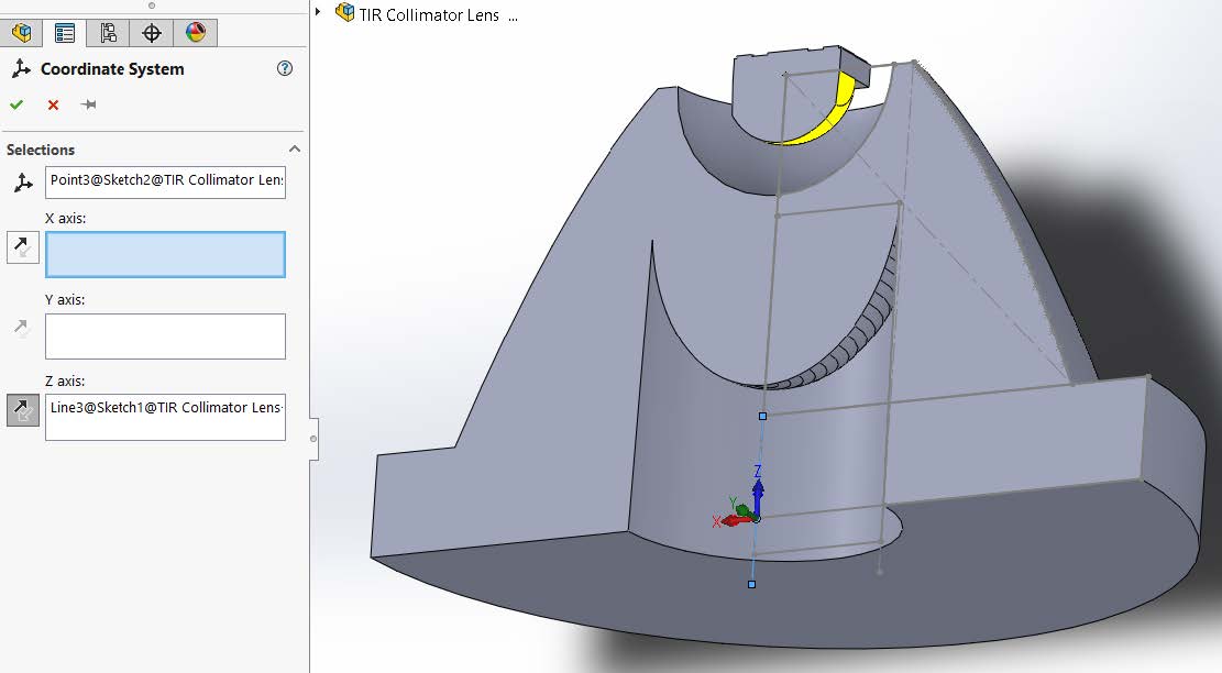
Add a reference coordinate system by going to Insert > Reference Geometry > Coordinate System. For the origin select the sketch point on the outside center of the lens (the point is on plane of the exit face of the flange of the lens, but centered in the central shaft cutout). The Z axis will be along the sketch centerline with +Z pointing towards the lamp (0° is towards -Z in IESNA photometric standards). Click OK ( ✔ ) to add the coordinate system
Select the new coordinate system and under the Photopia CommandManager select Photometric Settings. We will keep our default angle sets since the product is direct (0-90° vertical) and quadrilaterally symmetric (the square chip will be imaged throughout the lens). Click OK ( ✔ ) to save the Photometric Settings.
6. Assign Materials
Click on the Photopia Appearance Task Pane Tab:
In the search bar type “acrylic”, select the refractive generic acrylic material. Drag the material name onto the lens part in the model and assign it to the part level.
7. Raytrace Settings
Click on the Photopia CommandManager, select Raytrace Settings.
Keep the default of 2.5mil rays and 25 ray reactions.
Change the Sample Ray Count from 0 to 250 in order to see a sample of the 3D rays.
Click OK ( ✔ ) to save the raytrace settings.
Save the assembly
8. Run Raytrace
Run the raytrace
Click on the Photopia CommandManager and then select “Results”.
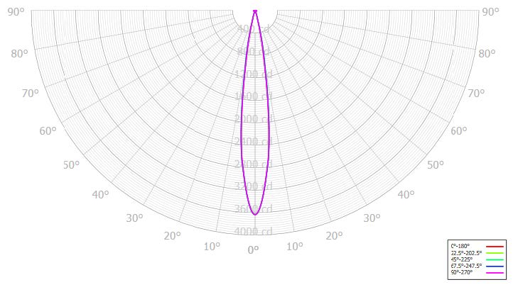
Click on the Photometric report and near the bottom you’ll see the beam angle (full width half max) is 14.9°.
Click on the the Intensity plot you’ll see the following candela polar plot
Under the raytrace report you’ll see the optical efficiency is 88.4%.