Advanced Tutorial: Air Duct Fluence
This tutorial will show how to install and setup Photopia for Rhino.
Skill Level
Advanced
Downloads
none
1. Setup Project
Open Rhino.
Set your project units to be in mm (type units in the command line which will open that option in the Document Properties window).
Save your model as Air Duct Fluence.
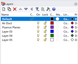
Change the name for Layer 01 to be Air Duct.
Change the name for Layer 02 to be Fluence Planes.
2. Create Air Duct
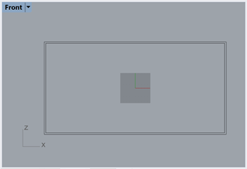
In the front viewport, draw a rectangle (typing rect at the command line) that is centered about the origin and is 600mm wide and 300mm tall.
Select the rectangle and offset by 5mm to the outside.
Change your current layer from Default to Air Duct.
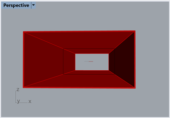
Select both rectangles, type extrude in the command line. For your options have BothSides=Yes and Solid=Yes. For the extrusion distance type 1500 which will make our air duct a total of 3m long (1500mm in each direction from the middle).
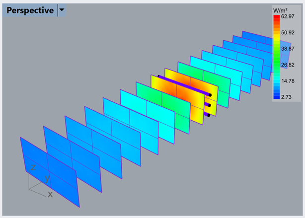
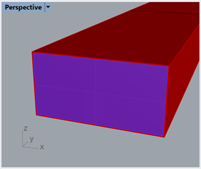
In the perspective viewport, change your display style from wireframe to shaded. Then orbit around and you can see your hollow air duct.
Select the solid air duct, click the Assign Materials button from the Photopia toolbar.
Search for galvanized and select the reflective generic galvanized steel material named Galvanized. Click the Assign selected material button.
Save your project
3. Add The Lamps
Click the Add Lamp button from the Photopia toolbar.
Search for TUV, and select the TUV-T8-18W-254nm lamp. Click the Add lamp button. Hit enter to use 0,0,0 (the origin) as the insertion point.
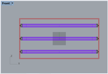
In the top viewport, select the lamp, type rotate in the command line. Enter 0,0 for the center of rotation and 90 for the angle.
In the front viewport, select the lamp, type copy in the command line. Enter 0,0 for the point to copy from and 0,100 for the first point to copy to, and 0,-100 for the second point to copy to. Hit enter to end the command. You will now have three lamps in your model spaced 100mm on center.
4. Setup the Raytrace
Click on the Raytrace Settings button from the Photopia toolbar.
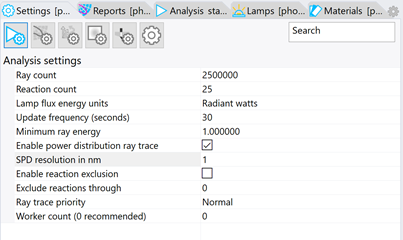
Change the Lamp flux energy units from Lumens to Radiant watts.
Change the Minimum ray energy to be 1 (this will stop any ray that reaches 1% of it’s initial magnitude, which will help the overall raytrace speed as the rays get reduced in magnitude as they bounce around within the air duct).
Check the enable power distribution ray trace option.
Set the SPD resolution in nm to be 1 since these lamps emit over a fairly narrow set of wavelengths.
We do not need to worry about the Photometric settings in this model because we are not using Photopia to generate standard photometry, instead, we are using Photopia to simulate the fluence in the air duct. So you should not use the IES file, candela table, or polar plot generated by this raytrace.
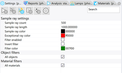
Under the Photopia Settings, click on the Sample ray settings tab.
Change the Sample ray count from 0 to 500.
Change the Sample ray length from 100 to 1000. This will allow you to see a sample of the 3D rays in the model view.
5. Add a Fluence Plane
Change your current layer from Air Duct to Fluence Planes.
In the perspective viewport, orbit so you can see the entrance (the -Y side) of the air duct.
Type edgesrf into the command line. For your first edge select the left inside edge of the air duct, for your second edge select the right inside edge of the duct. Hit enter to create the planar face.
Click the Add Recording Plane button from the Photopia toolbar. Select the new face at the entrance of the duct. For the name call it flu1 to represent the first fluence plane.
For the resolution in the U direction, type 24 so we have 24 columns that are each 25mm wide for a total width of 600mm.
For the resolution in the V direction type 12 so we have 12 rows that are each 25mm tall for a total height of 300mm.
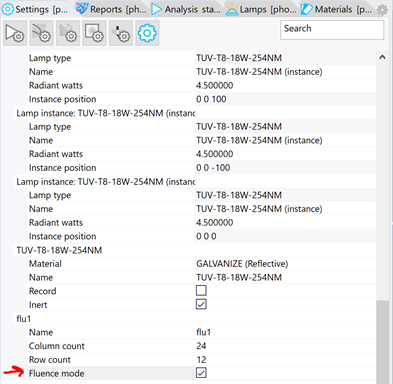
Select the plane, go to the Photopia Settings, and scroll to the bottom where you will see your new fluence plane. Check the box for Fluence mode.
Tip : What is Fluence
By checking the Fluence mode option you are specifying to Photopia how to handle the recording plane. For a normal illuminance plane Photopia records the incoming rays on the front face in each cell of the plane defined by the rows and columns.
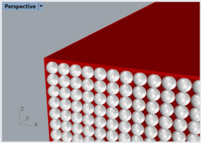
For fluence we place a recording sphere at the center of each cell defined by the rows and columns. Below is an image illustrating what that would look like behind the scenes, however you will still just see a simple plane:
Each sphere will record the total incident radiant watts from any direction. The spheres are only recorders and do not alter the ray’s magnitude or direction.
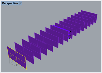
6. Array the Fluence planes
Turn off the air duct layer.
In the top viewport, select the entrance fluence plane. Type array into the command line. Type 1 for the number in the X direction, 16 for the number in the Y direction, and 1 for the number in the Z direction. Type 200 for the spacing in the Y direction. Press enter to accept. This will create a fluence plane every 200mm throughout the duct.
Turn back on the air duct layer.
Save the project.
7. Run the Raytrace
Click the Start Raytrace button in the Photopia toolbar or menu.
When the analysis is complete save the project.
Click on the View Results in New Window button in the Photopia toolbar. This will open your results in Photopia | Reports.
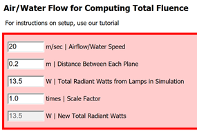
In Reports go to the Recorder report section and select the Recorder report - Fluence - FluidFlow option.
Here you will set the airflow, distance and total radiant watts emitted by the lamps. We will change the air speed in the duct to be 20m/sec airflow (a typical air speed). The spacing will stay at the default of 0.2m spacing since our planes were spaced 200mm on center). For the total radiant watts that number should be changed to be 13.5 to match the output of the 3 lamps.
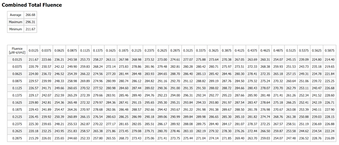
After updating each value the fluence table will automatically update. You will see the fluence for each cell across the plane, totaled for the entire length of the air duct. This assumes that the particle path is straight within the duct. You will also see the average, maximum, and minimum total fluence in µW-s/cm2.