Intermediate Tutorial: Use Grasshopper to Create an Extruded Surface
This Grasshopper definition produces an extruded surface given an input polyline profile. The profile can be manually drawn or created with Photopia’s parametric reflector or lens design tools (PODT). The benefit of using this definition with a PODT profile is that the surface properties will maintain their association with the profile as the PODT parameters are changed. The extrude direction is assumed to be along the world Y axis, so the profile should be created in the Front View. The surface can be made as a faceted polysurface or a single NURBS surface from a spline created through the polyline. The surface can also be symmetric or asymmetric. If symmetric, the mirror axis defaults around the front view Y-axis, but its location can be moved.
Skill Level
Intermediate
Downloads

OLD TUTORIAL
Beginning with Photopia for Rhino 2022, you can create extruded reflectors and lenses within the PODT tools directly.
Using grasshopper is not necessary, but you can use grasshopper to create more complicated surfaces, like the faceted reflector in this example
1. Download and Open the Grasshopper File
Download and save the Grasshopper file listed above in the Downloads section.
Open an existing or new Rhino model.
Choose Tools > Grasshopper and browse to the location where you saved the .gh file.
Open the Photopia-Extruded-Surface.gh file.
Tip : Save Location
We recommend saving all of your grasshopper files in an easy location to find later since you'll continue to add to your set of grasshopper files as you continue to use Photopia for Rhino.
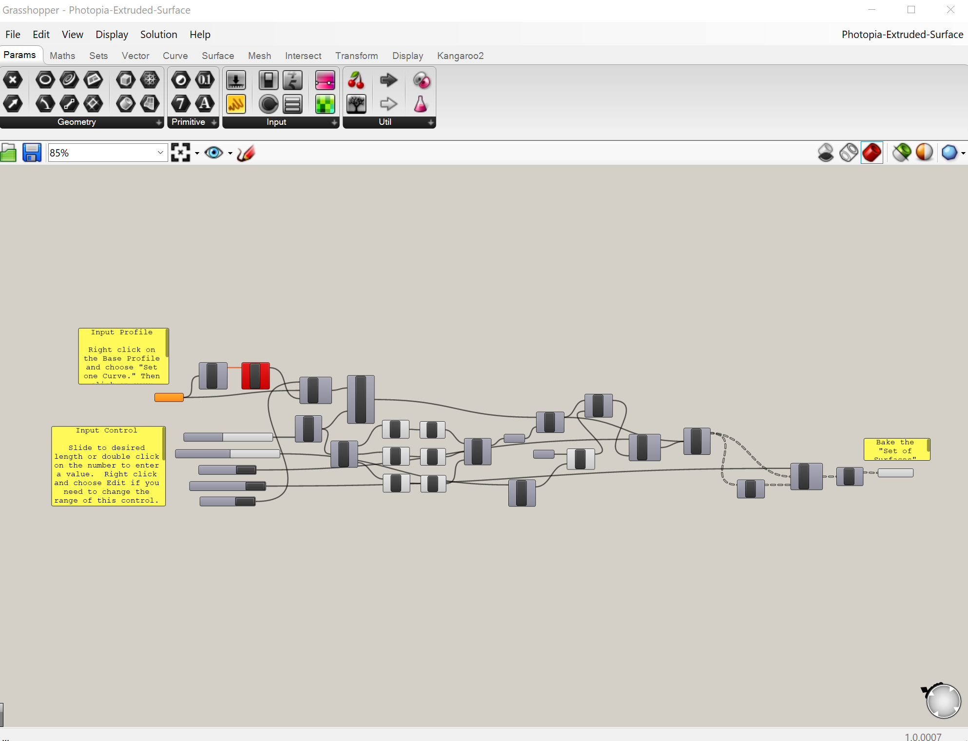
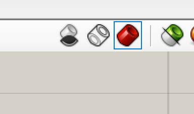
It’s best to open the Grasshopper definition on a second screen if you have one. This will allow you to see it along with your Rhino CAD model. To move around the canvas showing the components in the definition, right click your mouse over the canvas area to pan. Scroll your mouse wheel to zoom in and out. The general flow of information and logic is from left to right. You can also click on the drop-down arrow of the "eye" icon (shown below) and click the options to zoom in on the input parameters or the component to “bake” (save the surface).
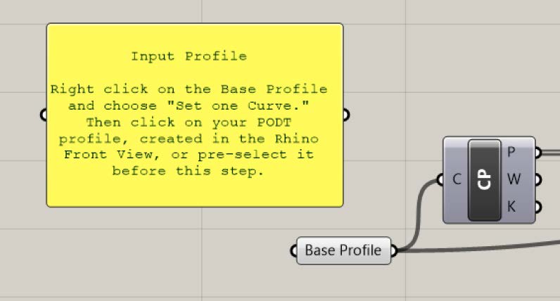
2. Associating Polyline Profile
Once the polyline profile is created either via Photopia’s PODT or manually, right click on the “Base Polyline” component and choose “Set one Curve” and then pick the polyline in the Rhino CAD view. You can also pre-select the profile before doing this step and the profile will automatically be associated after choosing “Set one Curve.”
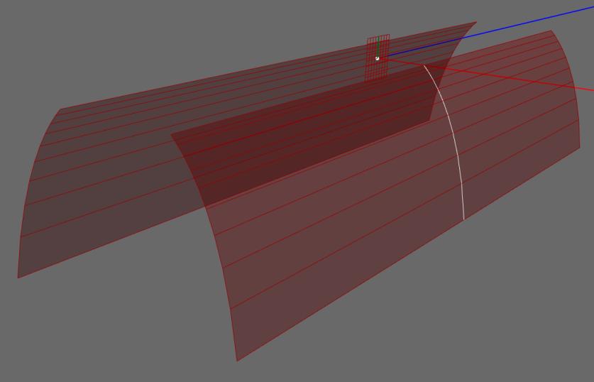
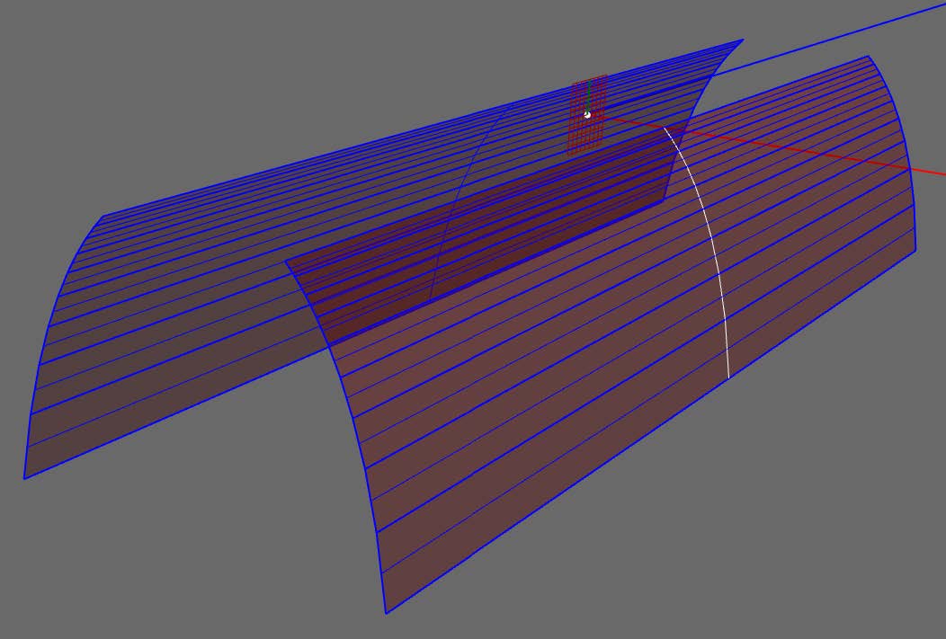
You will then see a preview of the extruded surface in your cad model. This red transparent surface is just a preview until you Bake it into the model in a future step.
3. Defining Input Parameters
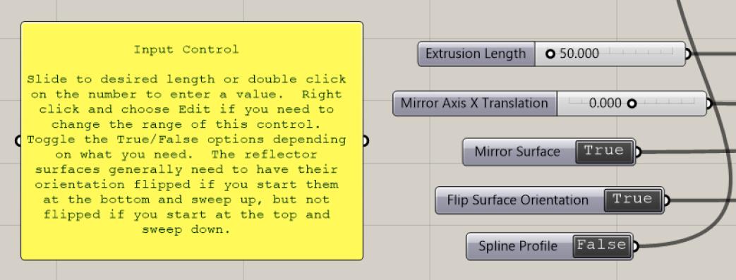
Use the slider & toggle controls to define all input parameters. You can enter exact values by double clicking on the number in the slider bar. If you need to change the range of values allowed in the slider, then select the control with a single left click, then right click and choose “Edit…” from the pop-up menu.
- Extrusion Length - The total length of the surface, centered around the profile location.
- Mirror Axis X Translation - The lateral shift of the default location of the mirror axis along the Front View Y-axis. A value of 0 keeps the mirror axis along the Y-axis.
- Mirror Surface - True means that the surface created from the profile will be mirrored. This is used for a symmetric optic. Set this to False for an asymmetric optic. Double click on the value to toggle between True and False.
- Flip Surface Orientation - True means the default surface orientation will be flipped. Reflector surfaces, for example, generally need to have their surface normals facing toward the origin (lamp point). Reflectors drawn with a positive angular extent require this to be set to True. After the surfaces are “baked” into the model, their surface orientation can be checked with the _ShowDir command.
- Spline Profile - When True, a spline will be created through the polyline points. This will result in a single NURBS surface being created from the profile. When False, flat/segmented surfaces will be created between each pair of points along the polyline profile. The individual surfaces are joined together into a single polysurface.
4. Baking the Output Surface
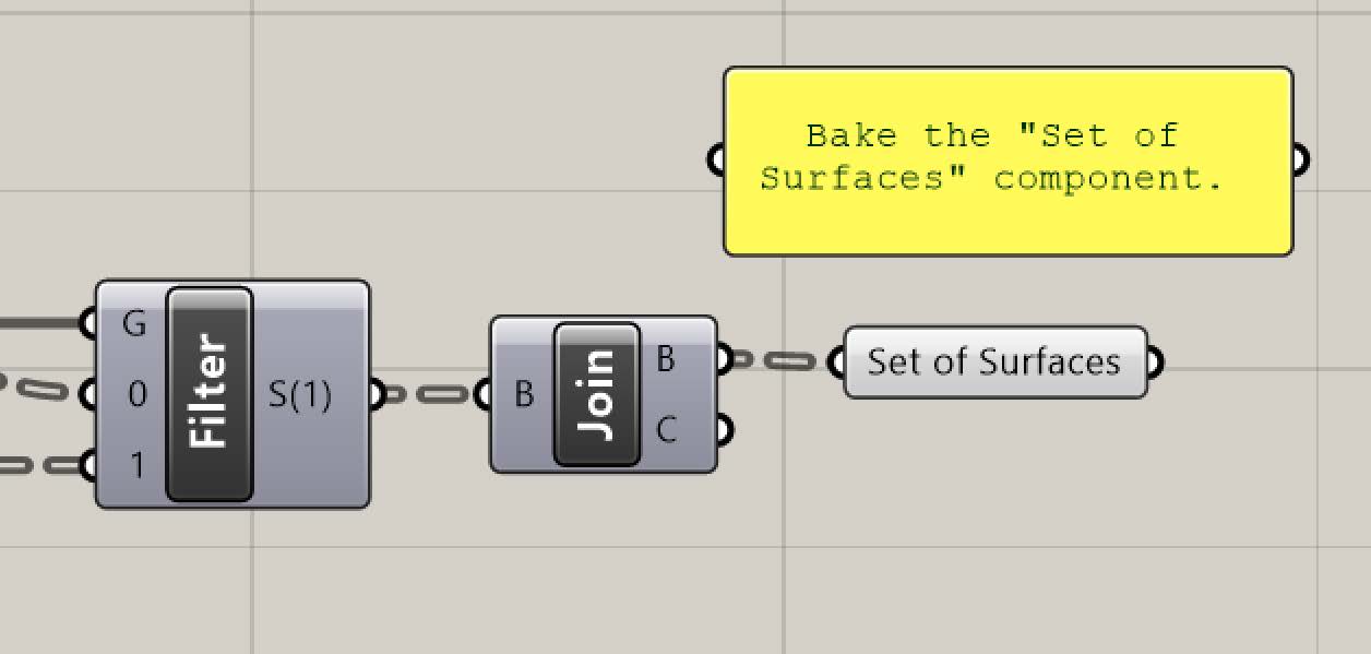
To save the surface the definition has created to your Rhino CAD model, right click on the “Set of Surfaces” component on the far right of the definition.
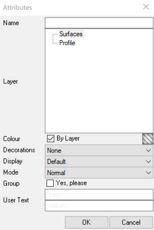
You’ll have the choice of the layer on which it is created, but it will default to the current layer.
The reflector should import as 1 or 2 polysurfaces, whether or not it is mirrored, with the surface normals pointed inward. You can flip the orientation if necessary, via Rhino’s “Show object direction” tool. If you needed to flip the direction, then you can toggle the “Flip Surface Orientation” option so that it correctly bakes the next time.
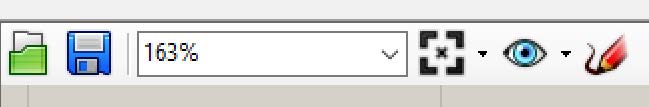
You can turn off the red preview of the Grasshopper surface by clicking on the left most icon below in the upper right-hand corner of your Grasshopper screen.
5. Photopia Simulation Notes
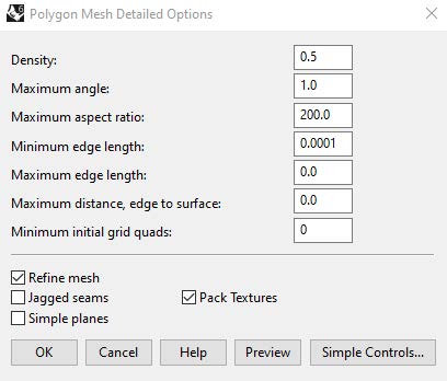
When using curved surfaces, be sure to set appropriate mesh resolution parameters using the “PhotopiaMeshSettings” command. You can run this command after assigning a Photopia material to the surfaces. If using smoothly curved surfaces, then use a small “Maximum angle” setting of 1° or less. You can enter a large “Maximum aspect ratio” for extruded surfaces to minimize the number of polygons in the mesh along the extrusion direction.
When raytracing this model in Rhino, you’ll need to reassign the Photopia material each time a new surface is baked from the Grasshopper definition since the Photopia materials are assigned to objects. This can quickly be done by selecting the surfaces and then selecting your previous material in the “Recently Used” section at the top of the Materials panel.