Advanced Tutorial: Optimize Light Guide Extraction Features
This tutorial includes a set of Grasshopper (GH) definitions that produce various types of light guide panel (LGP) extraction features.
Skill Level
Advanced
Downloads
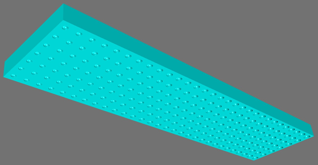
Types of Extraction Features
This tutorial includes a set of Grasshopper (GH) definitions that produce various types of light guide panel (LGP) extraction features.
Another tutorial includes a GH definition that produces an array of variable sized spherical cutout extraction features across any NURBS surface. The GH definitions included in this tutorial provide a range of other types of extraction features and can be used with a larger # of extraction features. The GH definition for NURBS surfaces requires more complex geometric operations, which limits the # of extraction features to about 500 and takes longer to process. The definitions in this tutorial support more extraction features and run faster since they are designed for flat & linear arrays.
Types of Extraction Feature Tools
There are a few general types of definitions included:
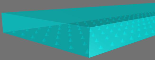
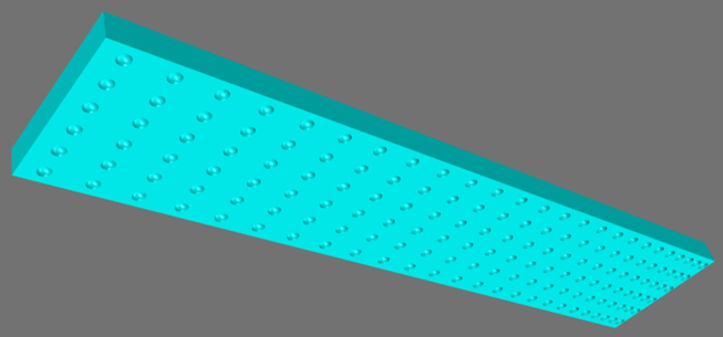
- Tools that produce the complete light guide surface with the extraction features included. You input the size and thickness of the rectangular panel.
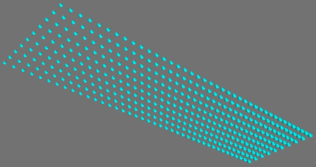
- Tools that produce only the extraction features. You can then subtract these extraction features from any solid LGP you construct in Rhino using the _BooleanDifference command. These tools are best when using a large # of extraction features since subtracting solids is faster in Rhino's CAD system than in GH. These tools can generate 5000 extraction features within a few minutes of processing time on a computer with 32GB of RAM. If you require a higher # of extraction features, then we suggest modeling a smaller section of your light guide to start, then expand upon it using Rhino's CAD system if necessary.
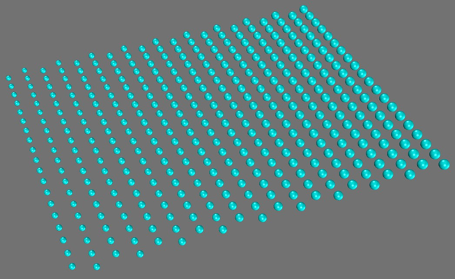
- Tools that work with “Brep” geometry as the extraction feature. A Brep is a “boundary representation” of geometry, which is any “solid” or “closed polysurface.” GH definitions using these include a “Brep” component at the start, which needs to be associated with the base extraction feature you construct. To do this, select your exaction feature in Rhino, then right click on the Brep component and choose “Set one Brep” from the pop-up menu. The extraction feature should be centered at the origin and scaled at your desired default size. You will define the scale factor range for variable sized extraction features.
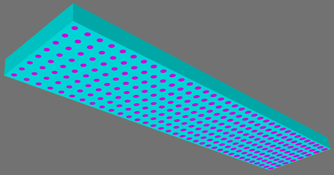
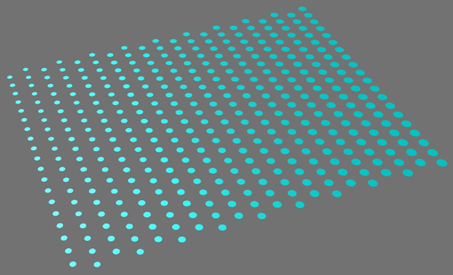
- Tools that produce dots (flat circular regions) cut out of the LGP extraction surface. These are generally used for printed dot patterns onto a smooth surface. The dot material properties vary from the base LGP material, causing light to enter and scatter within the dot material. The dots can also be used to create the pattern used for laser etching a LGP. In this case, we generally recommend that you model the extraction effects of the laser etched/roughened surface with hemispherical cutout features or construct an irregularly shaped solid feature to use with the Brep tools.
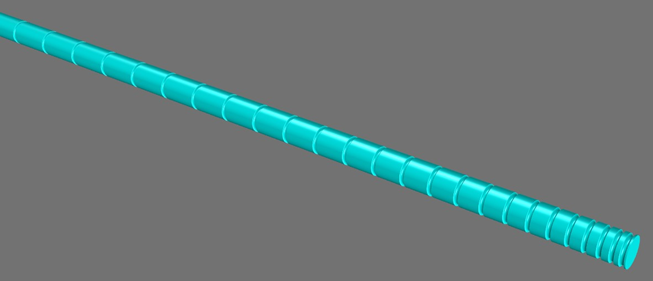
- The single row tool is useful when creating extraction features around the outside of curved surface such as a rod or polymer fiber. The example shown above used a torus as the extraction feature subtracted from a solid cylinder.
Variable Sized Features or Variable Spacing
Some of the GH definitions produce variable sized extraction features over a constant grid spacing that you define. You set the size/scale of the start and end features. You also set a “power” factor, which allows the sizes to change exponentially from the start to the end. Setting the power factor to 1 results in a linear size progression.
Other definitions use a constant sized feature and variable grid spacing across the light guide extraction area. You enter the relative feature spacing at the start and end of the array, along with the power factor that changes the spacing exponentially from the start to the end. Setting the power factor to 1 results in a linear progression of the change in feature spacing.
Intro to Grasshopper
If you've not used Grasshopper (GH) much yet, then we recommend that you watch some short videos to get a general introduction. There's a wide variety of good videos on this website:
https://thedifferentdesign.com/tutorials/
Scroll down to the section of the page with the introduction videos. We recommend starting with 1.01, 1.02 & 1.08.
Example Design
Download and unzip the following file included with this tutorial to the folder you prefer for your GH definitions.
LGP-Extraction-Features-GH-Files.zip
Also download and open the following Rhino V7 model:
Light-Guide-Panel-Example.3dm
To open a GH definition file from within Rhino, choose Tools > Grasshopper. From the GH window, choose File > Open and browse to the location of your GH definition files. Open this file:
Photopia Light Guide Extraction Features - Flat - All Surfaces - Spheres.gh
If you have multiple screens, then it's helpful to put the GH window on a different screen than Rhino. Otherwise, size the GH window to be about half of your screen so that you can see geometry in Rhino while setting the input parameters in GH. Right click your mouse to move around the GH view and roll your mouse wheel to zoom in & out. The general flow of data is from left to right.
Use the input values shown to the right. Note that you can enter an exact value in the slider bar control by double clicking on it. Press the Enter key to accept the value you've entered. You should see the red preview geometry update as you change the parameters. It might take a few seconds to update after each entry. To get quicker updates, first enter 5 & 10 for the # along the 2 edges, then enter their intended values last.
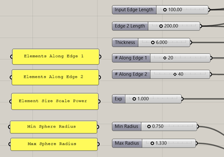
- Input edge length 100
- Edge 2 length 200
- Thickness 6
- # along edge 1 20
- # along edge 2 40
- Exponent 1.0
- Minimum sphere radius 0.75
- Maximum sphere radius 1.33
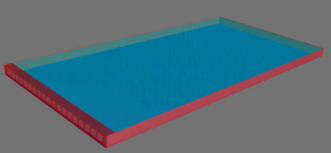
Baking the Output Surface
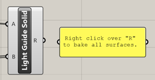
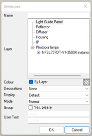
To save the light guide solid the definition has created to your Rhino CAD model, right click on the “R” output parameter of the “Light Guide Solid” component on the far right of the definition. You'll have the choice of the layer on which it is created, but it will default to the current layer, “Light Guide Panel.”
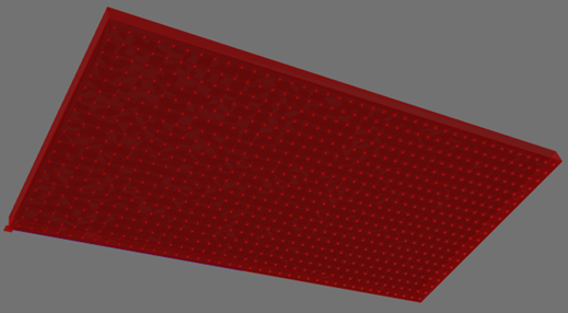
Tip : Preview Geometry
Rhino previews the resulting Grasshopper geometry as a red surface.
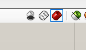
You can turn off the red preview of the Grasshopper surface by clicking on the icon circled below in the upper right-hand corner of your Grasshopper screen.
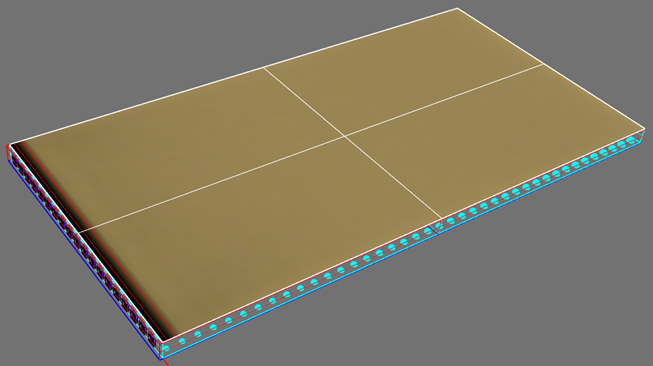
Simulating the Full LGP Model
The 3dm model used for this LGP includes geometry on other layers so that you can see how well it performs. To get the model ready to raytrace, select the LGP geometry and assign the ACRYLIC1 refractive material. Then turn on the rest of the layers for the housing, back reflector, diffuser, LEDs and the recording plane.
The raytrace is set up with 100 ray reactions. This works well for this LGP, but others might require several hundred ray reactions depending on geometry details. Ensure that you have a low percentage of light that “reached the ray reaction limit” in the Raytrace Report to confirm that you've traced enough ray reactions.
The extraction features of this LGP have been defined to produce a relatively uniform luminous surface. This now serves as a reference for the trend in the extraction features that you will use in other LGP designs.
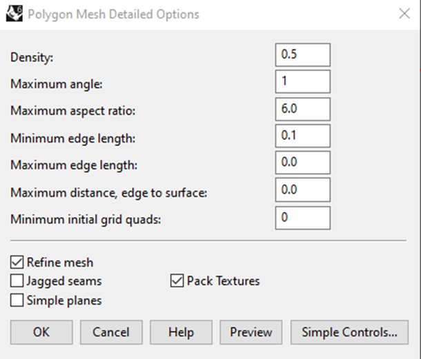
Photopia Simulation Notes
When using curved cutout features in a light guide, be sure to set appropriate mesh resolution parameters using the “PhotopiaMeshSettings” command. For a more accurate model, you'll need a small “Maximum angle” value to represent the cutout features. Also choose a reasonable “Minimum edge length” and preview the mesh to ensure it's acceptable.
When running the model within Rhino, you will need to reassign the Photopia material each time a new surface is baked from the Grasshopper definition since Photopia materials are assigned to object geometry directly.