Intermediate Tutorial: Design a Fresnel Lens
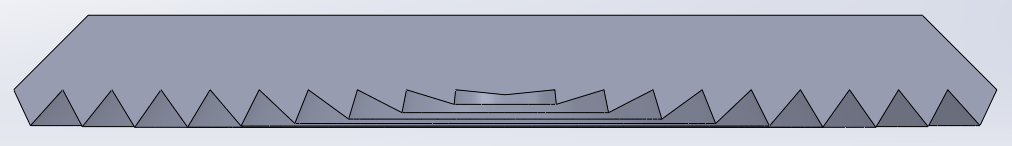
We will develop a standard Fresnel lens to collimate the light from a COB source into as narrow of a beam as possible. Fresnel lenses are useful in that you can achieve a narrow beam while keeping your lens thickness more uniform and easier to mold. Tradeoffs in these style designs can be seen with lower efficiency since the lens only controls a portion of the original distribution from the source, and less beam control since there is a fillet on each peak and valley connecting the prisms.
If you need to review the basics of Photopia for SOLIDWORKS, then start with the SOLIDWORKS Beginner Tutorial.
Skill Level
Intermediate
Downloads
none

1. Initial Assembly Setup
Open SOLIDWORKS and start a new Assembly document.
Make your assembly units in Metric (MMGS).
Save the assembly as “Fresnel Lens”.
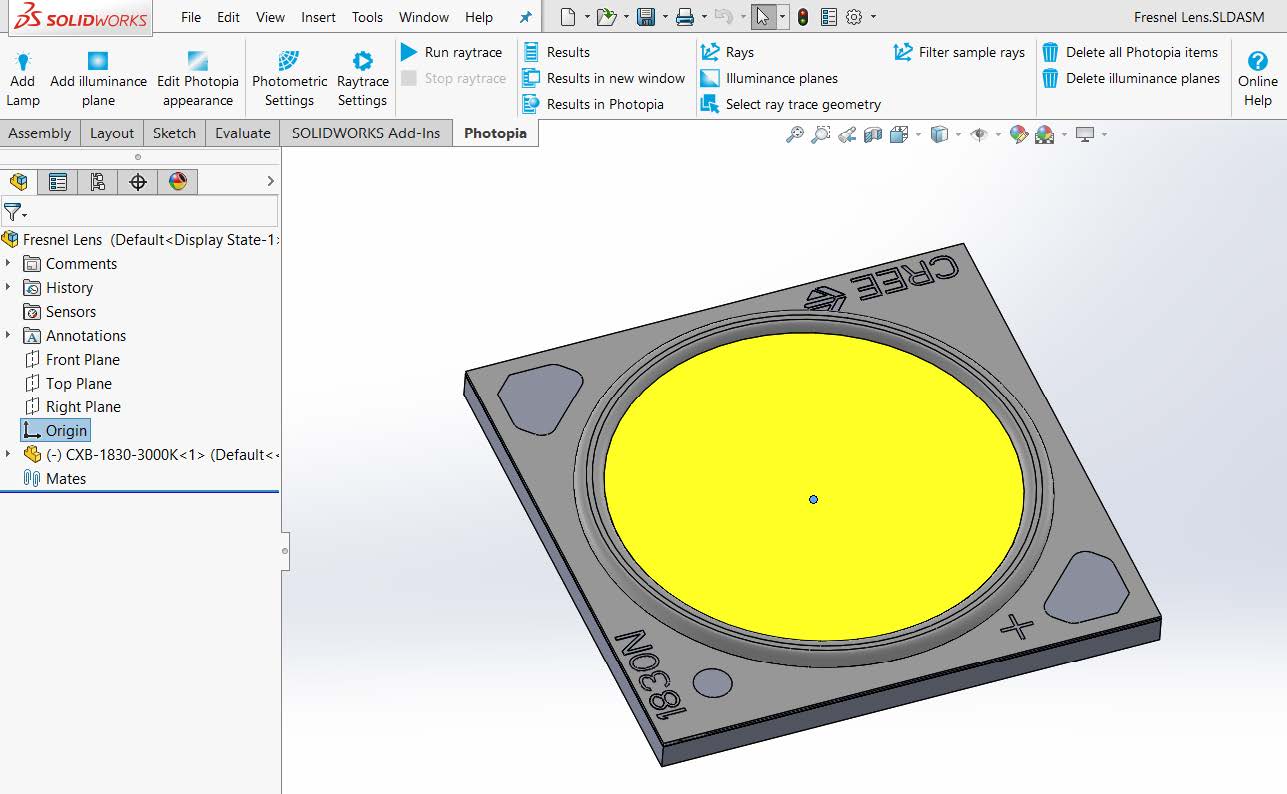
From the Photopia CommandManager, click “Add Lamp”.
Click on “Browse Lamps”. In the “Choose a Lamp” menu type “CXB” into the search bar, this will show all the lamps with “CXB” in the name. Double click on the “Cree CXB-1830-3000K” lamp designation. Click OK ( ✔ ) to insert the lamp at the assembly origin.
Right click on the lamp part and click on the "Fix" property to fix the lamp part in place.
Save the Assembly.
2. Define Lens Constraints
Go to File > New, and select a new part document.
Make your part units in Metric (MMGS).
Save the part as “Fresnel Lens”.
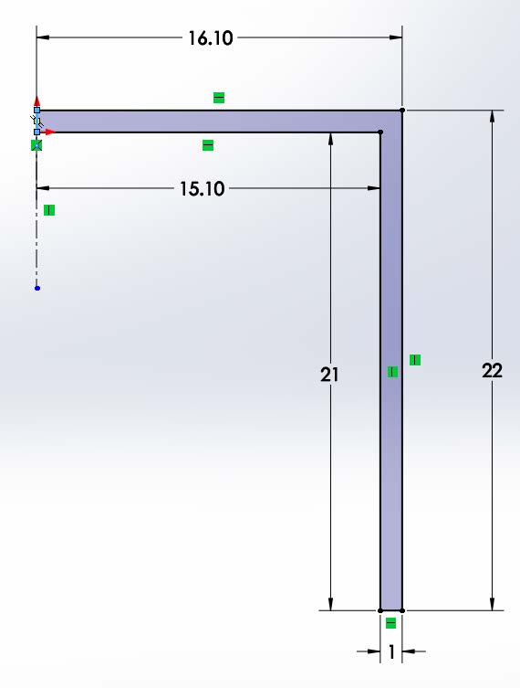
Begin a new sketch on the Top Plane.
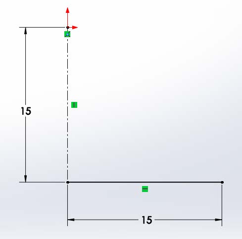
Draw a centerline from the origin straight down. Make the centerline 15mm long. The centerline will define our lamp center, and our 0° aiming direction.
Draw a line from the bottom of the centerline, straight to the right. Make the line 15mm long (so the lens will be 30mm in diameter). This line will serve as our "base profile" to create the revolved Fresnel lens.
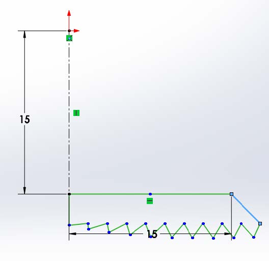
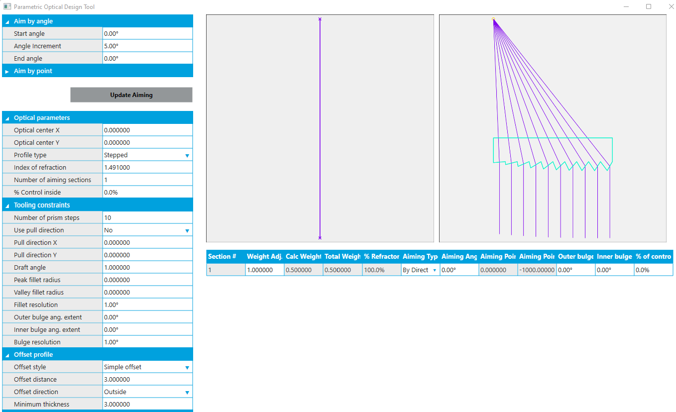
3. Create Lens Profile
Click on the Photopia CommandManager and select “Design Lens”.
The Lamp Center is the origin at the top of the centerline.
The base profile is the horizontal line.
We will keep the default number of Prism Steps at 10
We will keep the default Index of Refraction at 1.491 for generic acrylic.
Additionally we will keep the default Minimum Thickness at 3.00mm.
The edge to define the 0° aiming angle is the centerline.
Last, our goal is to create a beam as narrow as possible, so we'll keep the start and end aiming angles of 0° along with the 5° angle increment (which does not matter here since we have the same aiming angle at the start and the end of the base profile). Click OK ( ✔ ) to complete the lens design.
4. Revolve Lens Profile
Click on the Features CommandManager and select “Revolved Boss/Base”. The Axis of Revolution is the centerline and we will use Blind and 360° Direction1 settings. Click OK ( ✔ ) to complete the revolved feature and close the sketch.
5. Associate PODT with Revolve Feature
In the FeatureManager Design Tree select the “Revolve1” feature.
Click on the Photopia CommandManager and select “Design Lens”.
Under “Reload” select the PODT Refractor that you designed, and Click OK ( ✔ ) to connect that design profile to the revolve feature, allowing you to adjust the profile in the future without recreating the feature.
6. Update Lens Properties
We'll change the "Offset style" so that the outer profile has the same radius as the base profile.
Select the “Revolve1” feature, go to Photopia > Design Lens, and click “Open the PODT Window”.
In the "Offset profile" section, set the "Offset style" to "Simple offset" from the dropdown list.
Close the PODT window and click OK ( ✔ ) to update your lens profile.
Keep in mind that when making changes to the PODT optical profiles, all non-construction sketch entities will be deleted and replaced with new sketch entities. So avoid creating any references (constraints & mates) to the non-construction sketch entities.
Save your part.
7. Add Lens to Assembly
Go back to your Fresnel Lens assembly.
Click on the Assembly CommandManager, select “Insert Component”,
select the Fresnel Lens part and click OK ( ✔ ) to add it to your assembly.
As you will see the lens will be added to the model but behind the lamp and facing the opposite direction. We must flip the lens around.
Right click on the lens and click on the "Float" property to change it from being fixed in place.
Select the lens and under the Assembly CommandManager, select Rotate Component (an option under Move Component).
Chose by delta XYZ for the rotate option and 180° in the Y axis. Click OK ( ✔ ) to commit the rotate.
Mate the lamp origin to the lamp center of the lens sketch.
Under the FeatureManager Design Tree, expand the Fresnel Lens part, right click on the sketch and select the option to show the sketch.
Click on mate. Your first point will be the lamp center point from the part sketch. The second point will be the origin from the CXB-1830 lamp part. This will move the lens slightly forward relative to the lamp.
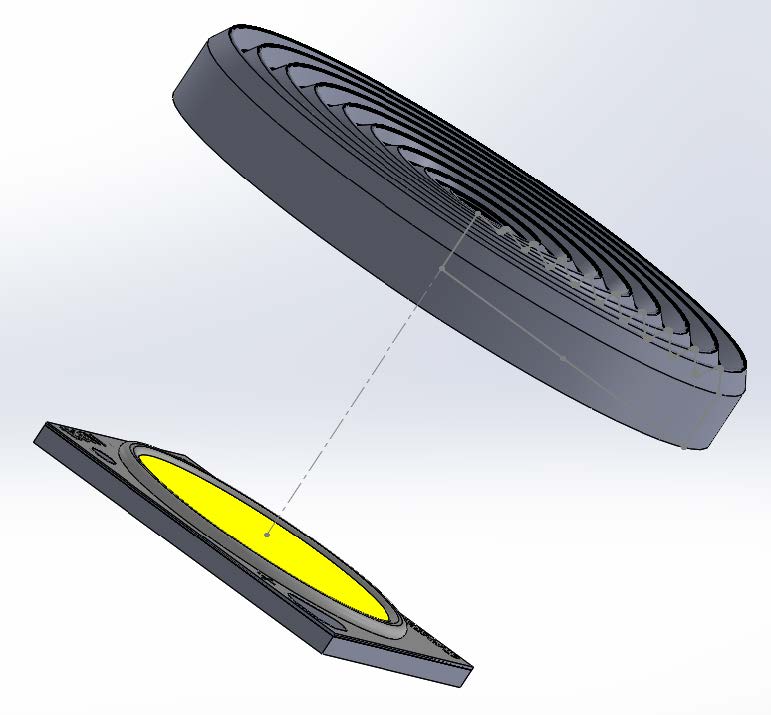
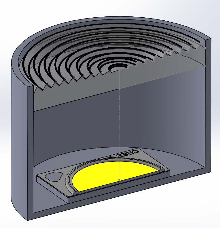
8. Create a Simple Housing
Start a new part for a simple housing that will block light not emitted through the lens.
Create a sketch for a simple cylindrical shell that will enclose the COB and lens.
Revolve the sketch to create a solid part and save as “Housing”.
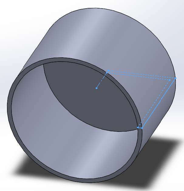
In the Fresnel Lens assembly insert the Housing part and mate it so the inside horizontal face of the housing is mated with the back face of the COB and it is centered with the COB/lens.
9. Setup Photometric Settings
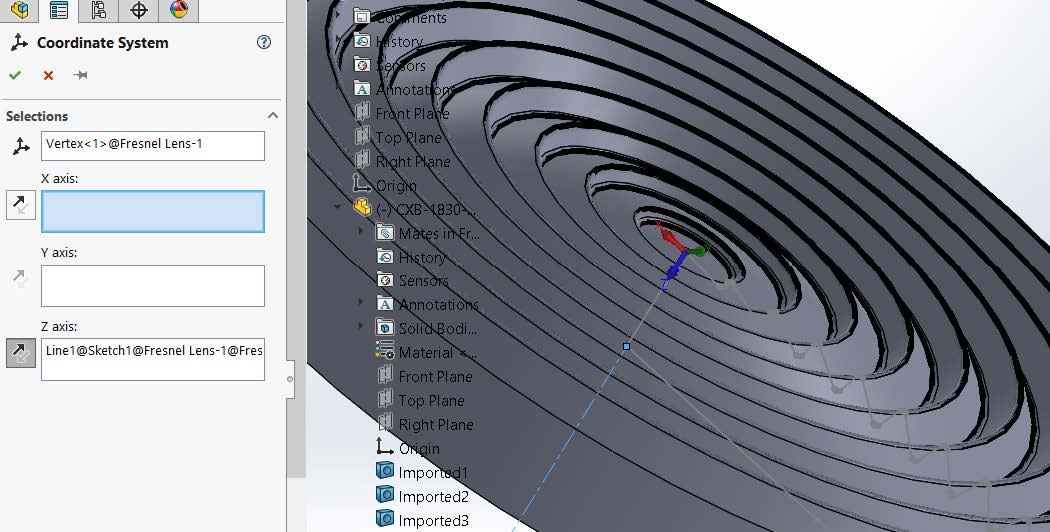
Add a reference point to the center of the circular opening of the housing. This will be used to locate the photometric coordinate system, which should be in the center of the lens emission surface. We want to avoid using the Fresnel lens geometry as a reference however, since it will be deleted and re-created when making design changes to the PODT lens.
For the origin, select the new reference point you've just added.
The Z axis will be in line with the assembly Z axis.
Click OK ( ✔ ) to add the coordinate system.
Select the new coordinate system, then click the Photopia Settings button on the Photopia CommandManager. Since the optic is axially symmetric, our horizontal angle set will be just “0.” Since the optic produces only downward directed light, our vertical angle set will go from 0° to 90° in steps of 5°. Click OK ( ✔ ) to save the Photometric Settings.
10. Assign Photopia Appearances
Assign the refractive Generic Clear Acrylic material to the lens part.
Assign the reflective Generic Flat Black material to the housing part
Open the Photopia Appearances Task Pane on the right side of the screen.Type "Acrylic1" into the search box and choose the Generic ACRYLIC1 refractive appearance and assign it to the lens part. It's important to assign it to the lens part rather than faces or a body since those will be deleted and re-created when making design parameter changes.
Type "flat black" into the search box and assign the reflective appearance shown to the housing part.
11. Confirm Raytrace Settings
Click on the Photopia CommandManager, select Raytrace Settings.
Keep the default of 2,500,000 rays and 25 ray reactions.
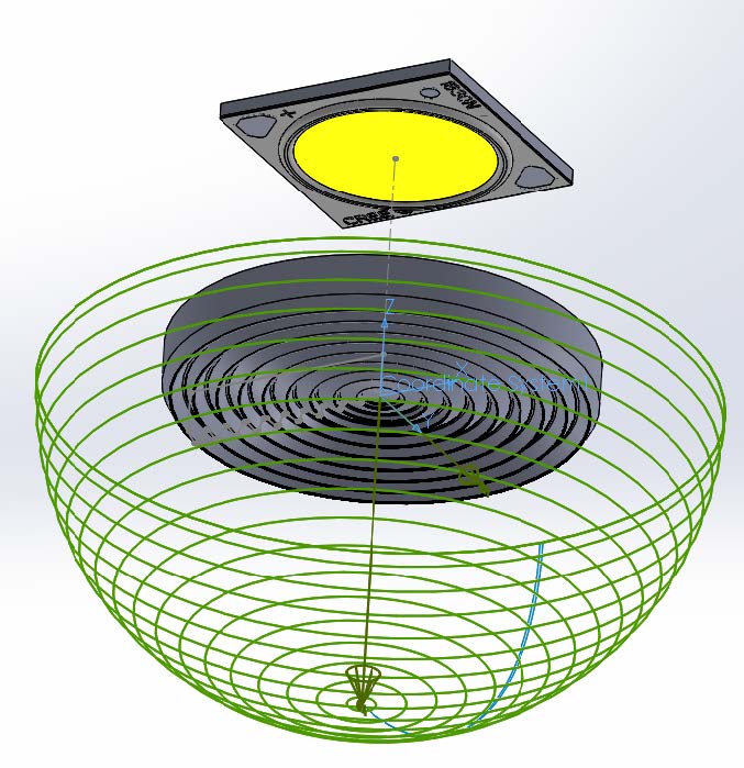
Change the Sample Ray Count from 0 to 250 in order to see a sample of the 3D rays.
Click OK ( ✔ ) to save the raytrace settings.
To ensure that the raytracer gets accurate meshes of your solid model geometry, go to the SOLIDWORKS System Options screen and choose "Imaging Quality" on the Document Properties tab. Move the upper slider in the red zone.
12. Run Analysis and View Results
Save the assembly.
Run the raytrace
View the results
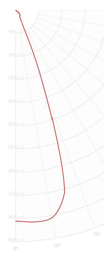
A beam angle (full width half max) of 37.8° has been achieved, narrowing the beam significantly from the 120° lambertian beam emitted from the COB.