Intermediate Tutorial: Air Duct Fluence
This tutorial will demonstrate how compute fluence for a UVC based air duct disinfection system.
Skill Level
Intermediate
Downloads
none
1. Setup Project
In Solidworks, create a duct of the appropriate size. Typically, the duct should have at least 1 m before and after the UVC lamps.
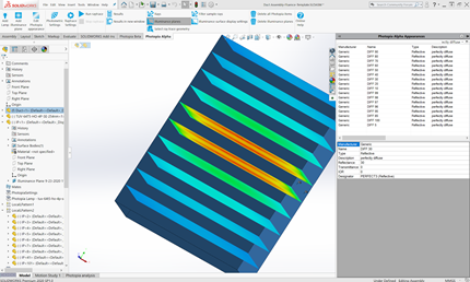
Assign the Photopia 30% Perfectly Diffuse material to the duct. (Photopia Appearances tab on the right, search for Perfectly Diffuse, click and drag onto the Duct Part.)
Add the UVC lamps to the project. (Add Lamp > Browse to find lamp, add Lamp, place in appropriate locations within the duct.)
2. Add Fluence Planes
Create a plane that is the entire cross section of the ducts.
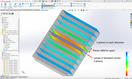
Pattern this plane before and after the lamps. A good starting point is to create planes that are 200mm apart and extend 1 m before and after the lamps, with the first planes 100mm from either side of the lamps.
3. Assign Fluence Planes
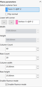
Select each plane and choose Add Illuminance Plane / Add Recording Plane. Ensure the “Enable Fluence Mode” is selected. Set the row/column count or row/column spacing as you wish for the resolution. A good rule of thumb is 25mm x 25mm. Each plane must be the same for the Inactivation Rate graphs to work.
Tip : What is Fluence
By checking the Fluence mode option you are specifying to Photopia how to handle the recording plane. For a normal illuminance plane Photopia records the incoming rays on the front face in each cell of the plane defined by the rows and columns.
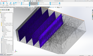
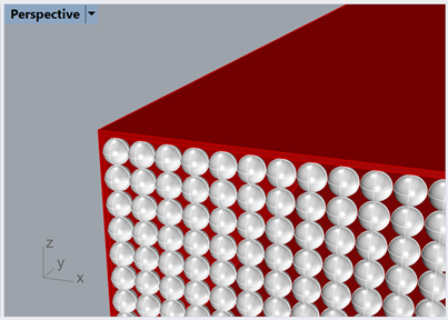
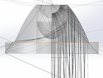
For fluence we place a recording sphere at the center of each cell defined by the rows and columns. Below is an image illustrating what that would look like behind the scenes, however you will still just see a simple plane:
Each sphere will record the total incident radiant watts from any direction. The spheres are only recorders and do not alter the ray’s magnitude or direction.
4. Run the raytrace
Click Run Raytrace to begin the simulation.
5. View Results
Click on the View Results in New Window button in the Photopia toolbar.
On the left, go to the Recorder report section and select the Recorder report - Fluence - FluidFlow option from the drop down.
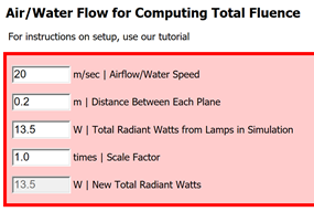
Here you will set the airflow speed and distance between the planes.
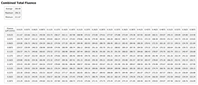
After updating each value the fluence table will automatically update. You will see the fluence for each cell across the plane, totaled for the entire length of the air duct. This assumes that the particle path is straight within the duct. You will also see the average, maximum, and minimum total fluence in µW-s/cm2.