Intermediate Tutorial: recording objects
This tutorial describes how to define an object recorder and view the results with different display options. This can be done for any 3D surface and the displayed values are highly configurable.
Object Recorder: A way to collect data on any 3D object, which must have a Photopia Appearance assigned. Grid/Resolution is defined by the mesh provided by Solidworks.
Illuminance Plane: A flat rectangular plane to collect data on. Grid is defined by number of rows and columns.
If you need to review the basics of Photopia for SOLIDWORKS, then start with the SOLIDWORKS Beginner Tutorial.
Skill Level
Intermediate
Downloads

Some of the object recorder display options.
1. Define an Object Recorder
An object recorder can be any 3D surface in your model.
- Select one or more faces or objects in your model.
- Click "Add Illuminance Plane / Add Recording Plane" from the Photopia CommandManager tab. Note that if a flat face is selected, then Photopia will default to a standard illuminance plane, not a 3D Recording object. If you want a flat surface to be a 3D surface reorder, then choose it along with other non-flat surfaces and it will then be treated as a 3D Recording object.
- After a raytrace is complete, click on the "Illuminance Planes / Recording Planes" button in the Photopia CommandManager to display the Illuminance Planes and 3D Recording objects.
- The "Illuminance surface display settings" button on the Photopia CommandManager tab allows you to specify the way the recorders are displayed. See the "Display Options" section below for more details.
Object Requirements
You must select the same level of geometry to which the Photopia appearance was already assigned. If the appearance was assigned to a face, then select the face, not the full part that includes the face.
Object Recorder vs. Illuminance Plane
If a flat face is selected, then Photopia will default to a standard illuminance plane, not a 3D Recording object. If you want a flat surface to be a 3D surface reorder, then choose it along with other non-flat surfaces and it will then be treated as a 3D Recording object.
Mesh Resolution
Unlike Illuminance Planes, the resolution of recording objects is defined by Solidworks. See the section below for more details on setting the mesh resolution.
2. Display Options
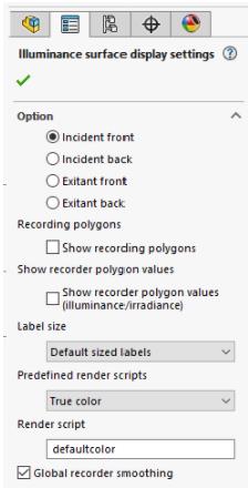
Click on the "Illuminance surface settings" button on the Photopia CommandManager to see the display options.
Surface To Display
The Option/Channel allows you to view any of 4 data sets on the surfaces. The options are the incident light onto the front and back sides of the surfaces as well as the exitant (emitted) light from both the front and back sides. All 4 channels are available for recording objects, but only on the front incident light channel is available for illuminance/recording planes. In Solidworks the front is the side on the outside of a solid body, the back is the side on the inside of a solid body.
Recording Polygons & Values
These options allow you to view the recording polygons (grid cells) to confirm the cell size is appropriate and view the actual numerical values for each cell.
Predefined Render Scripts
Select from the dropdown of Predefined render scripts to choose between true color, gray scale and false color for various metrics. They also allow you to choose spectral shift options, such as viewing UVC wavelengths transformed into the visible range to evaluate both magnitude and spectral mixing outside the visible range. To evaluate color uniformity, you can choose the "Delta u'v' from average" option.
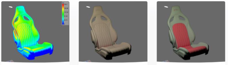
Left imageFalse color incident illuminance.
Center imageTrue color incident illuminance from a 4000K LED.
Right imageTrue color exitance reflected off the seat from 4000K LED and spectral reflectance of slate gray main seat with cherry red cushion & logo.
Render Scripts
Once a preset render script is selected, then the render script will be displayed in a separate box. All values of that render script can then be edited to manipulate the recorder display even further.
Global Smoothing
The "Global recorder smoothing" option determines whether the data on each patch is blended with neighboring patches. Smoothing the data makes a more realistic looking image of the light pattern. If you turn off the smoothing, then you see the raw data in each patch of the recorder.
Scale
By default, all planes will be scaled to the global max value found on all planes. The global max is automatically found when the "Global scale max" parameter is set to 0 in Rhino. You can enter any other value there if you prefer. A legend is displayed when using global scaling and viewing gray scale or false color plots. If you uncheck the "Global scale enabled" box in Rhino or switch to local scaling in the SW Photopia general settings screen, then each recorder will be scaled according to its own max value. A legend can't be displayed in this case since the same colors will represent different magnitudes.
Delta u'v' from average
The "Delta u'v' from average" plot allows you to view quantitative color differences in the uniform u'v' color space. In this color space, a value of 0.001 is 1 MacAdam ellipse, which is a just perceptible color difference. Beam color uniformity requirements sometimes specify an allowable range in this color space, such as 0.004 or 4 MacAdam ellipses. In this plot, black is 0 and bright green is the highest delta u'v' value on the plane. This plot type supplements the true color plot when color differences in the light pattern are subtle, especially for tunable white lighting applications. Since this metric compares color data, you will need to run a signficant number of rays to get reliable u'v' values (50M+).
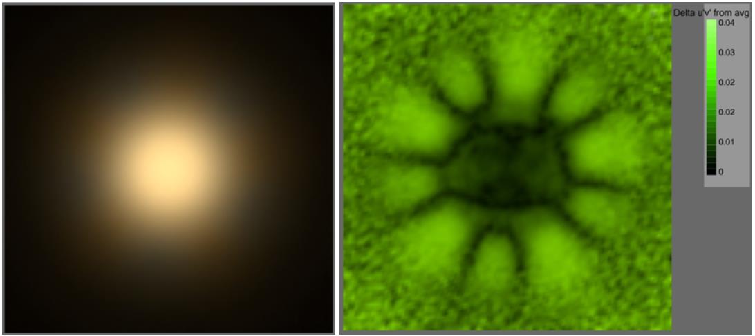
Left imageTrue color image of beam. Subtle color variations are seen around the beam perimeter. LED array uses 7 2700K and 7 5000K LEDs.
Right image"Delta u’v’ from average" plot of illuminance plane. This plot shows the quantitative color variation over the plane. Perimeter color variations are now very clearly identified.
3. Mesh Resolution
The mesh resolution on the part will define the resolution of the 3D Object Recorder on that part.
The default way to adjust Mesh Resolution on a part in Solidworks is to go to Settings / Document Properties / Image Quality. Slide the top bar labeled "Shaded and draft quality HLR/HLV resolution" into the red zone for a finer mesh.
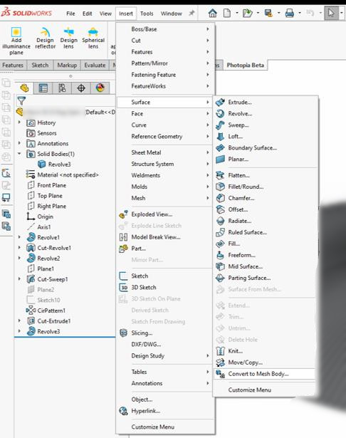
To define more detailed mesh settings in SW, you can add one or more "mesh body" features to the part. This feature was introduced in SW2018. In your part, choose Insert / Surface / Convert to Mesh Body...
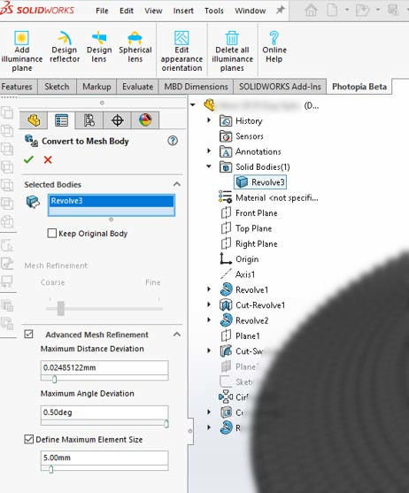
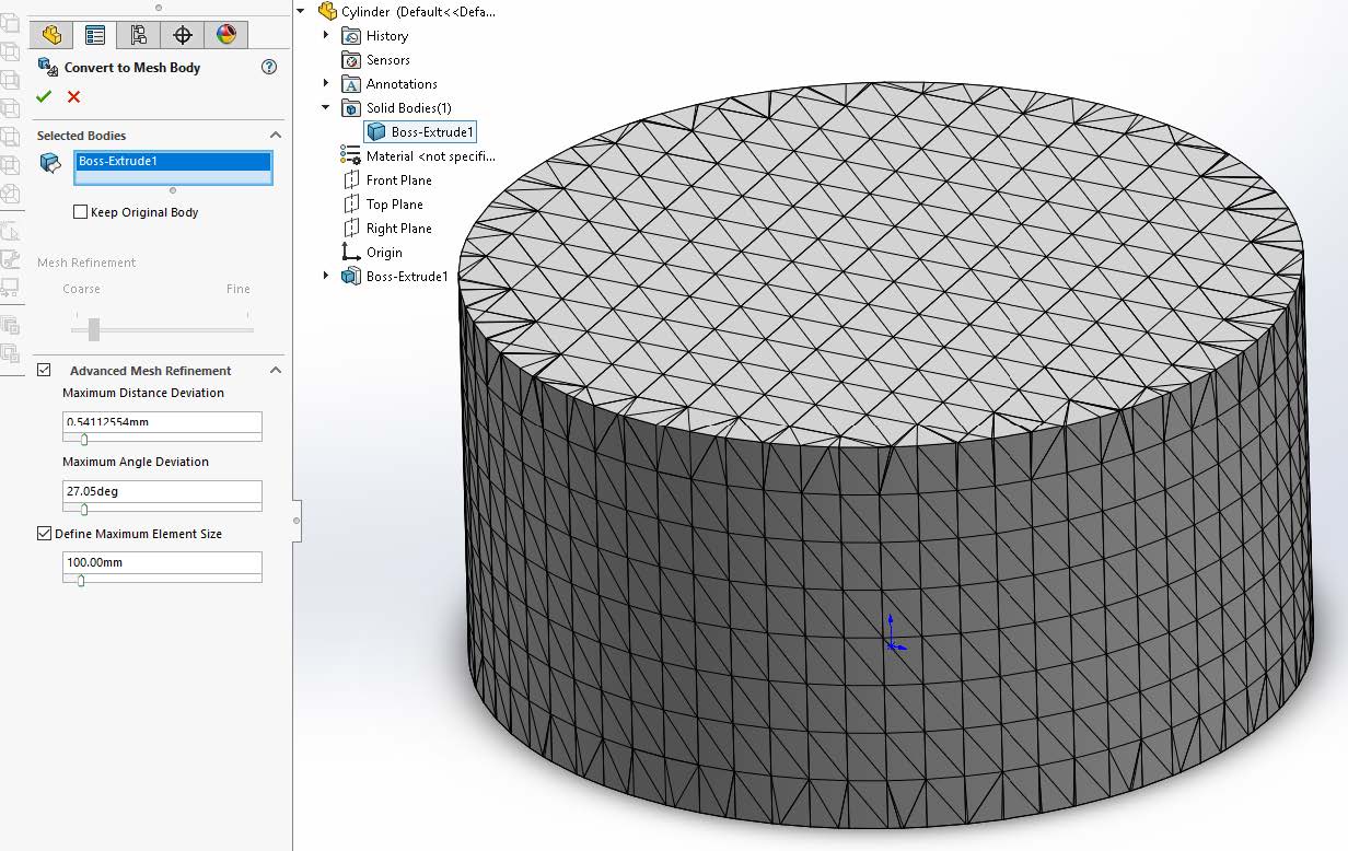
Check the Advanced Mesh Refinement and Define Max Element Size boxes to expose properties to set the max angle deviation and max element size. The important parameter when surface curvature is critical is the max angle deviation, which we recommend setting to 0.5°. Note the default option for Keep Original Body will be unchecked. This creates a new feature in the FeatureManager. As other features are modified in the part, the mesh will be rebuilt on the new body. The mesh parameters can be modified by right clicking on this feature just like any other feature in the part.
If you leave the “Keep Original Body” option unchecked, any mates made to this part body will be broken. If the original body is retained, then be sure to assign the Photopia appearance to the mesh body rather than the entire part, otherwise the part geometry will be replicated during the raytrace, with meshes created for the original part solid as well as the mesh body.
When defining an “object recorder” that allows you to see the incident and exitant light onto both sides of all surfaces of the object, we first recommend that you add meshes to the bodies of the object so you can confirm the data resolution is appropriate for your application. In this case, using the “max element size” is often the best choice. Once the mesh is created, then assign the Photopia appearance to the “convert to mesh body” feature. The Photopia appearance needs to be assigned to the same level of geometry as is specified as the recorder.
To define the "object recorder," first select the "convert to mesh body" feature and then click the "Add illuminance plane / Add Recording Plane" button on the Photopia CommandManager. This will show the property management page that lists the selected objects.
The object must have a Photopia appearance assigned to it to be used as an object recorder.
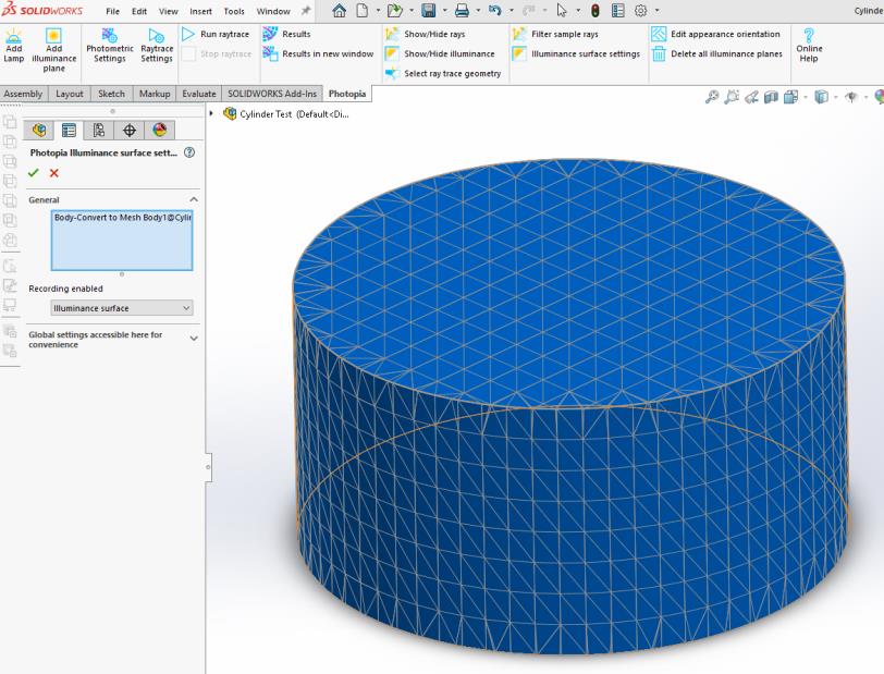
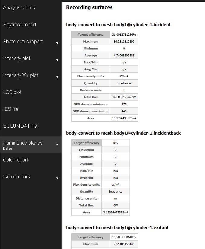
The results for the object recorder can be viewed in the CAD view with the same options as viewing illuminance/irradiance planes. Note that the back side of the surfaces face to the inside of the body.
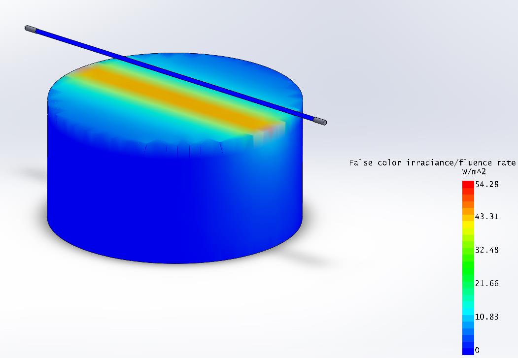
Statistics for the recorder can be seen in the "Illuminance planes" report. The statistics are for the entire mesh. If the mesh body was created from a solid body, then a single mesh will be made for all surfaces of the solid. If you prefer to see the statistics for individual faces, then build the object from surfaces instead. In the case of the cylinder, the top circular face would be one surface (Insert/Surface/Planar) and the vertical sides a separate surface (Insert/Surface/Extrude). Both can be made from the same sketched circle. A surface may not be required for the bottom if the object is resting on the floor or a shelf.