Beginner Tutorial: Import a STEP File
This tutorial will show how to import a STEP file into Rhino.
Skill Level
Beginner
Downloads
1. Create a new Rhino file
Start Rhino and choose File > New ... from the main menu.
Go to File > Save and give your project a name.
Tip : Setup Rhino First
If you haven't yet installed, setup or licensed Photopia for Rhino, follow the Rhino Setup tutorial first and then come back to this tutorial.
Install, Setup and Licensing Tutorial2. Import the STEP File
Go to the File menu and select Import.
Browse to find the LED_Collimator.STEP sample file for this tutorial, which you can download above.
Click OK on the Step Import message about nested block instances.
3. Explode the Block
Select the imported object, it will turn yellow.
Type ExplodeBlocksToLayers at the command line to initiate this command.
Your object will be exploded onto individual layers that represent the assembly model structure, including sub-assemblies.
Rhino imports STEP and IGES models as a set of nested blocks that represent your assembly part structure.
Clicking on the light bulb icon turns on and off layers/parts in Rhino's Layers panel. Sub-assemblies are shown as layers with sub-layers, and turning off the top layer turns off the sub-layers as well.
4. Orient the Model
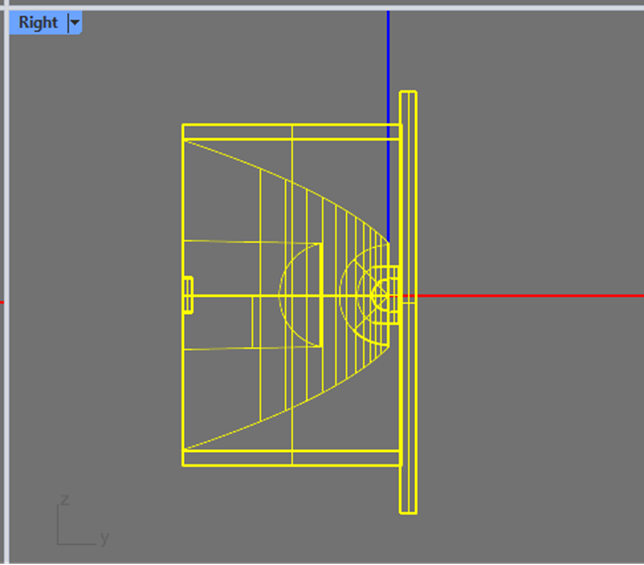
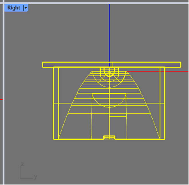
Go to the right view.
Select the entire model using a crossing window, it will turn yellow.
Type Rotate at the command line.
Type 0,0 as the point to rotate about.
Type 90 as the angle to rotate.
Original Orientation:
Corrected Orientation:
Photopia's photometric coordinate system is set up by default in Rhino so that the 0-degree vertical angle is oriented toward the -Z world axis. The photometric coordinate system can be re-oriented if desired, but we generally recommend keeping the default orientation and rotating your CAD model appropriately.
4. Setup and Run the Simulation
Follow our next tutorial to setup the rest of the model for analysis.