Advanced Tutorial: UVC Disinfection Chamber
This tutorial shows how to run an analysis in Rhino to determine the irradiance onto all surfaces of objects inside of a UVC disinfection chamber. This is a useful simulation since the data allows for the determination of the time required to achieve a desired UVC dosage. This chamber uses an array of low pressure mercury (LPM) lamps and anodized aluminum wall reflectors.
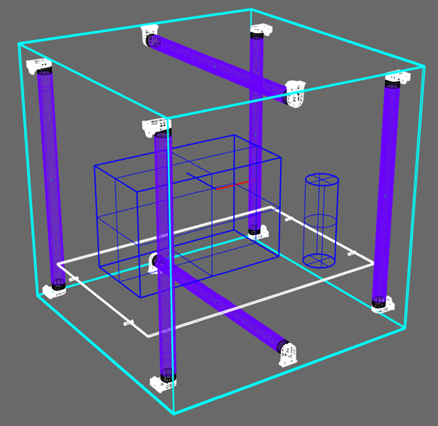
The model includes a 0.5m x 0.5m x 0.5m chamber, a glass shelf, 2 objects sitting on the shelf and an array of LPM lamps.
Skill Level
Advanced
Downloads
1. Open the Rhino Model
To open this model, choose File > Open and browse to the location where you’ve saved the UVCDisinfectionChamber.3dm file, which you can download above.
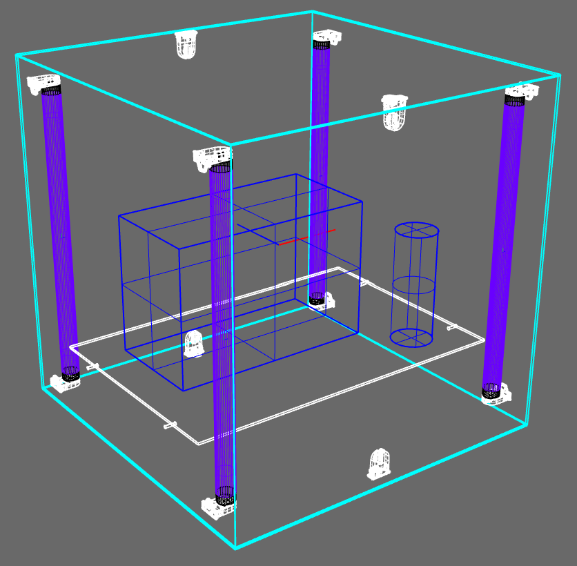
The initial model will have all of the objects show in the image below. It requires 2 more lamps to be placed above and below the objects on the shelf. This model is meant to represent the relevant optical surfaces for the design and not be an accurate mechanical model. An actual UVC disinfection chamber of this type would have one of the side surfaces swing open as the door. In this model, either of the sides without lamps mounted to them could serve as the door surface.
Tip : Setup Rhino First
If you haven't yet installed, setup or licensed Photopia for Rhino, follow the Rhino Setup tutorial first and then come back to this tutorial.
Install, Setup and Licensing Tutorial2. Defining Model Settings
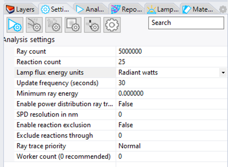
Open the Analysis Settings.
Change the Ray Count to 5,000,000 instead of 2,500,000
Change the Lamp flux energy units to Radiant watts instead of lumens
Open the Sample Ray Settings.
Change the Sample ray count to 500 instead of 0
Leave all other settings at their defaults.
3. Select the Photopia Lamp Model
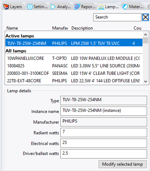
Click on the Lamps Panel.
Since the lamp type we want to place is already in the model, it will be listed in the “Active lamps” section at the top of the search box.
Click on that lamp type to select it. Since the project units are Radiant watts, the lamp output is specified here in Radiant watts.
Click Add Lamp to begin placing the lamp model.
4. Place the Photopia Lamp Model
The center of the lamp will be 229mm below and above the model origin to match up with the existing lamp holder locations.
Enter 0,0,-229 for the lamp insertion point.
Repeat this process, but using 0,0,229 for the lamp position.
You can also insert the lamp a single time and use Rhino’s CAD tools to move, copy and array it however you require.
Tip : Locating the Lamp
There are two ways you can place the lamp in the model:
- Drag and drop the lamp into the model by moving and left clicking your mouse.
- Enter the lamp coordinate into the command prompt.
The optic center of an LED model is typically located in the center of the chip emission surface.
5. Assign Material to the Chamber Walls
All surfaces of the chamber will be assigned an 88% reflective specular material to represent an anodized aluminum surface.
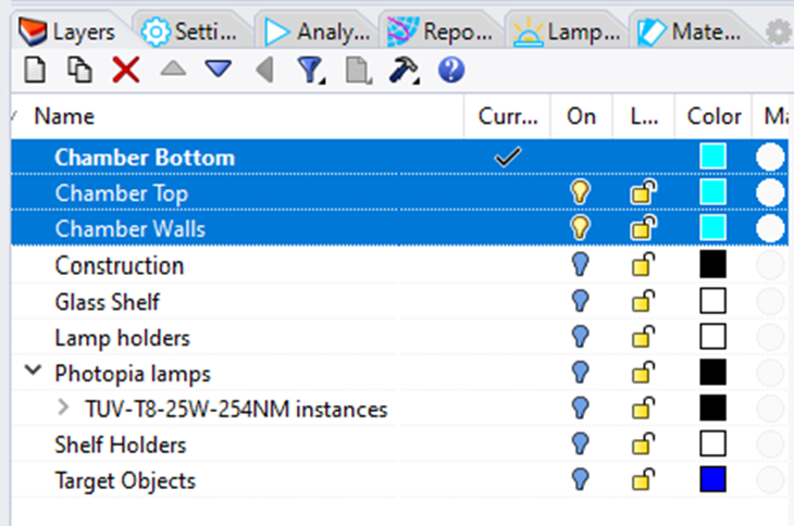
First turn on only the chamber layers and ensure all other layers are off.
Select all chamber objects by dragging a selection window around them in the CAD view.
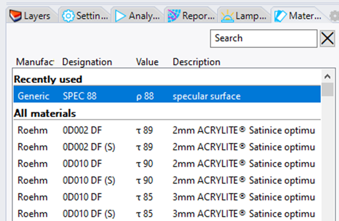
Click on the Materials Panel. and type "spec 88" in the Search box to find the Generic Specular 88% Reflective material. Double click or click "Assign Material" to assign the material.
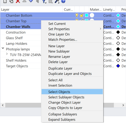
Tip : Select Objects by Layer
Instead of turning on and off layers to select the objects, you can also select the 3 layers, then right click on the layers and choose "
6. Assign Other Materials
Select the Glass Shelves in the CAD model.
In the Materials Panel. search for fused silica
Click on the Fused Silica 193-3710nm material.
Select the Lamp Holders, Shelf Holders & Target Objects in the CAD model.
In the Materials Panel. search for diff 10
Click on the 10% perfectly diffuse material.
Tip : Recently Used Materials
At the top of the search results, you'll always see your recently used Materials.
Tip : Spectral Materials
Materials with descriptions that include a wavelength range have data that varies by wavelength. So this refractive material has a variable index of refraction and extinction coefficient by wavelength, which is important so the raytrace has the most accurate information for this lamp with most of its emission at 254nm. Also note that there are few lens materials that transmit well in the UVC range, so be sure to make appropriate choices for these types of designs.
7. Define Recording Surfaces
Photopia can record the illuminance or irradiance onto each side of any optical surface in the model as well as the exitance on each side of the surface. The option to record is in the surface’s properties. In order to make it easier to interpret the data that will be reported for all of the recording objects, we’ll confirm the surface orientations, their names and their mesh resolution.
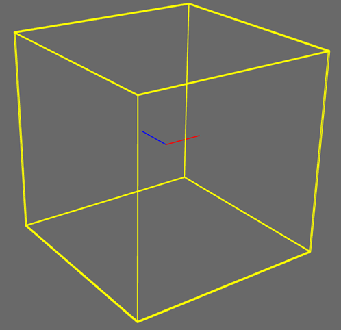
The surface names can be set in Rhino’s own properties panel. They are pre-defined in this sample model and you can see their names in Photopia’s Settings panel under the Object settings icon. The “Box Front” surface is selected below.
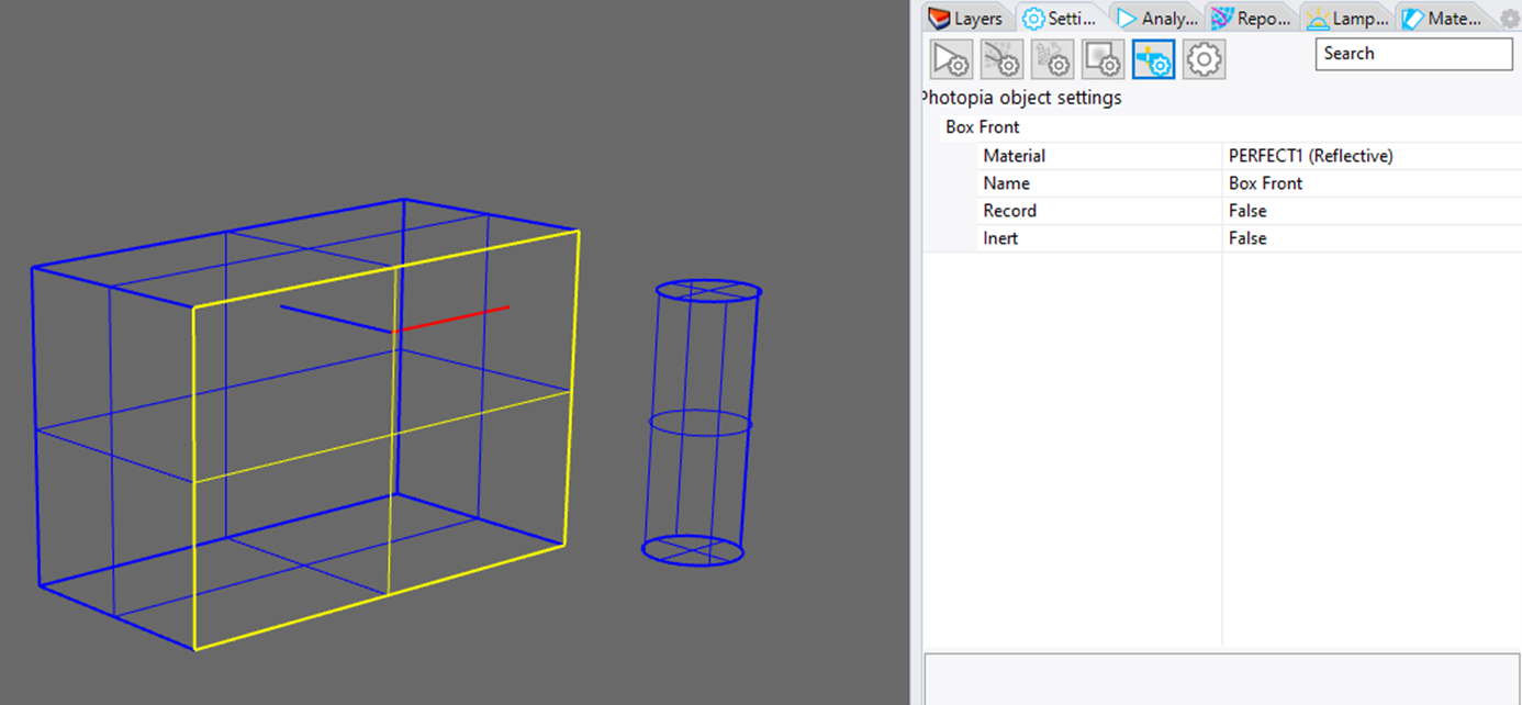
While the properties are being shown for this surface, click on the “False” setting for the “Record” property to change it to “True.” Now this surface will be setup as a recorder. Click on each of the surfaces of the box cylinder one at a time and set all of their “record” properties to true. You can also see the names of each surface while they are selected.
Tip : Surface Orientation
Photopia uses Rhino's surface orientation to know the inside and outside of each recording surface.
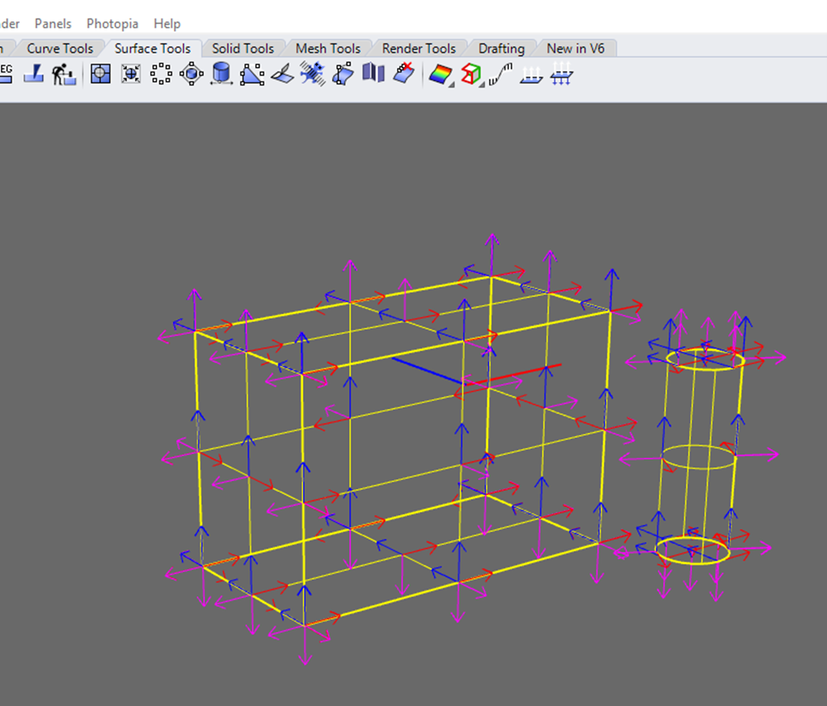
To confirm the surface orientations, select the objects and then click on the “Show object direction” icon on the Surface Tools panel as shown below. The magenta arrows are indicating the surface normals of the “front side” of the surfaces. Now we are certain that the front side is facing to the outside of these objects. This is a result of how they were created, as both objects are exploded solids. Use the pop-up dialog if you ever need to change surface orientations.
8. Specify Surface Mesh Resolution
The raytrace will be run on meshes that represent the NURBS surfaces used to define the parts of this model.
Click Mesh Parameters in the Photopia Toolbar or menu.
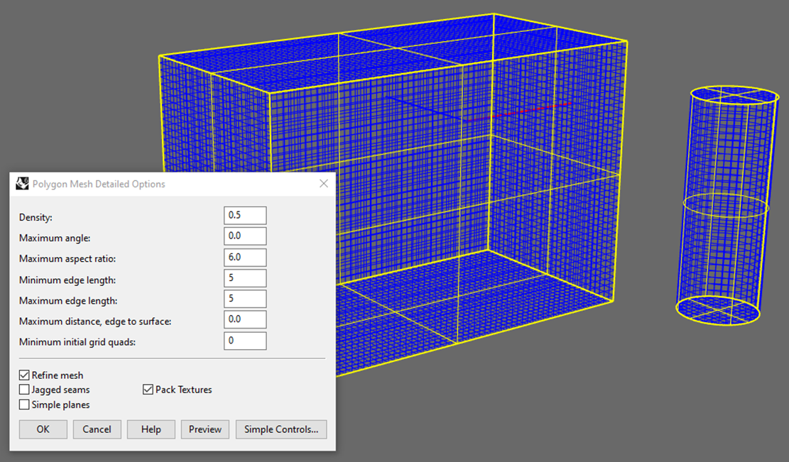
Click Detailed Controls... to open the expanded controls.
Change the Minimum Edge Length and Maximum Edge Length to 5 to specify a 5x5mm grid.
Click Preview to confirm the settings before clicking OK to accept the settings.
Tip : Mesh Resolution
A '0' value, means that parameter is non-controlling and other parameters take precedence.
These mesh settings apply to all optical geometry except for lamps, as they are based on their own internal meshes.
9. Start the Raytrace
Before starting the raytrace, ensure that all layers with optical components are turned on. For this model, that means all layers except for the Construction layer.
Click Start Raytrace in the Photopia Toolbar or menu
The Analysis Status Panel will automatically open so you can follow the raytrace progress.
This raytrace will likely take a few minutes to finish, depending on your computer speed.
Tip : Off Layers
Any layer that is off will not be included in the raytrace, even if it has a Photopia property assigned.
10. View the Results
Click View Results in the Photopia Toolbar or menu
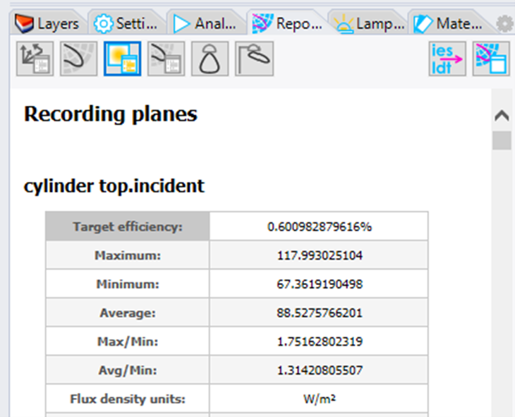
The Reports Panel has buttons for viewing a few simple reports.
The Recording Planes Report includes detailed statistics for the max, min, average, etc. on each of the recording objects
Tip : In Rhino and External Reports
The Reports Panel has buttons for viewing the following:
- Raytrace report
- Intensity plot
- Recording plane report
- Intensity table
- Indoor summary
- Outdoor summary
- Export IES/LDT file
- View results in Photopia Reports
You can view other report types in Photopia Reports, including our full photometric reports, standard reports and additional plot styles.
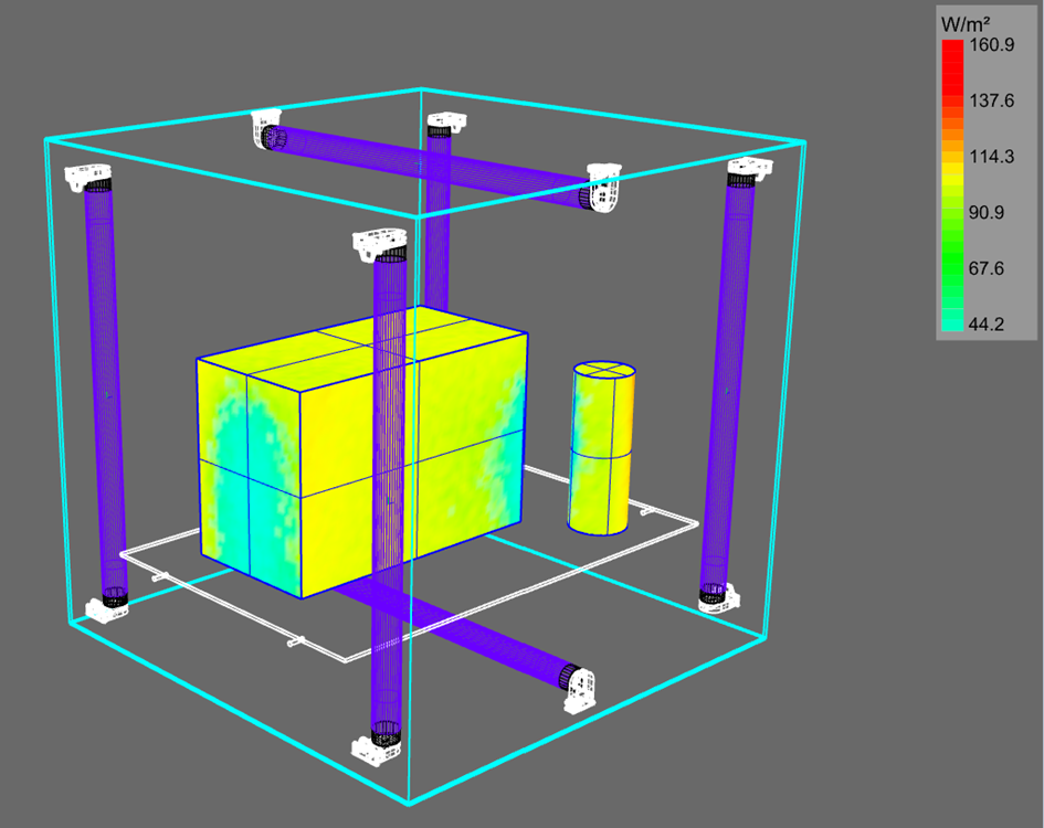
11. View the Results in the CAD Model
Click Show/Hide 3D Rays in the Photopia Toolbar or menu to show the 3D Rays in the CAD model.
Click Show/Hide Recording Plane in the Photopia Toolbar or menu to show the Recording Plane in the CAD model.
Click Recorder Plane Settings in the Photopia Toolbar or menu. Change the Global render script preset to False color irradiance and ensure that Channel is set to Incident Front
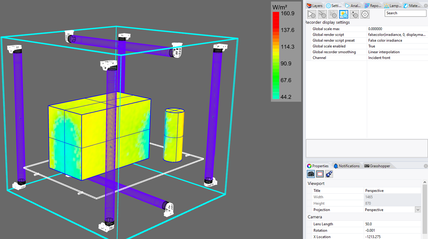
Tip : Recording Plane Magnitude
The legend for these results shows a minimum value of 44.2 W/m2. Most UVC dosage values are reported in milli-joules per area, commonly using mJ/cm2. You can convert from W/m2 to mW/cm2 by multiplying by 0.1. Photopia has therefore shown the minimum irradiance to be 4.42 mW/cm2. Since watts are the flow rate of energy in joules/second, you can get the dosage in joules by multiplying the irradiance by the exposure time in seconds. Conversely, if you know the dosage you want, then you can determine the exposure time it will take to achieve by dividing dosage by the irradiance.
For the specific example of deactivating COVID19, the International Ultraviolet Association (IUVA) currently recommends a dosage of 3000 mJ/cm2 for a 99.9% kill rate. You can read more on their website. That means the objects in this simulation will need to be irradiated for 3000/4.42 = 678.7 seconds or 11.3 minutes. Note that this is using a chamber with 150W of LPM lamp power and thus provides a general reference for the amount of UVC energy it takes to accomplish this type of disinfection.