Intermediate Tutorial: Create a Revolved PODT Reflector
In this tutorial you will design a 40° beam medium flood reflector using the Parametric Optical Design Tools (PODT) and the CREE CXA 3050 COB LED. This tutorial assumes you know how to setup and run a Photopia analysis inside of Rhino. If you need to review the basics of Photopia for Rhino, then start with the “Run an Analysis” tutorial.
Skill Level
Intermediate
Downloads
none
1. Start a New Model
Start Rhino with a new file and set the units to mm.
2. Choose a Construction Plane
Select the Front construction plane (cplane) and make it full screen. The profile will be constructed in this plane with the beam center toward the cplane -Y axis. This construction will create a reflector oriented in line with the default photometric coordinate system.
Tip : Construction Planes
Photopia’s PODT module creates reflector and lens profiles in any construction plane you choose. The profiles are based on several geometric constraints and aiming parameters that you will define. 3D surfaces based on these profiles are then created by modifying the PODT object properties. When you change the PODT object parameters, both the profile and surfaces are updated.
3. Create the Reflector
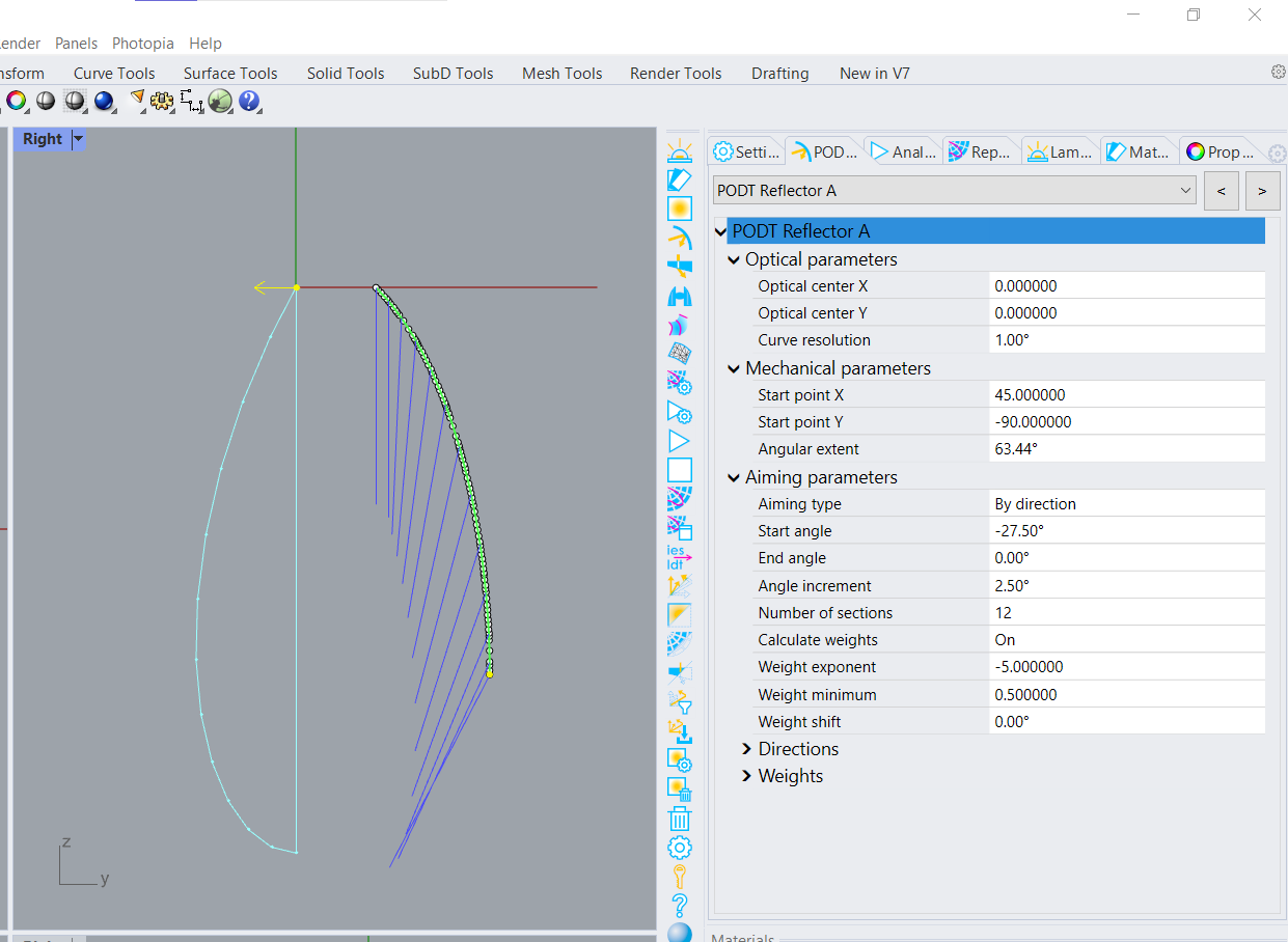
Click Design reflector on the Photopia toolbar. Accept the default of 0,0 for the Lamp center property.
Press Shift and move your mouse down, then left click to pick the Nadir direction to be in line with the -Y axis. Enter 45,-90 for the Start point.
Press Shift and move your mouse to the right along the X axis, then left click to pick the Angular extent.
Enter “D” for the Aiming type.
Enter -30 for the Aiming Start.
Enter 0 for the Aiming end.
Enter 2.5 for the Aiming increment.
Enter “S” to skip opening the PODT screen.
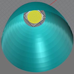
Your reflector should look like the one shown here. You might need to zoom extents in order to see the full reflector.
The image below shows references for the Aiming Nadir, Angular Extent, and Aiming Angle Directions.
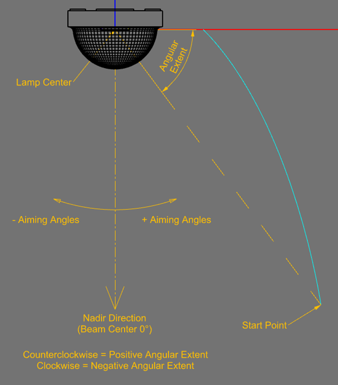
The Angular extent sweeps from the start point to a radial line that defines the end of the reflector.
The aiming angles define how you want to aim the light from the reflector. The goal of this design is to create a 40° beam angle, which means the 50% intensity values will be 20° to either side of the beam center. The peak intensity for this design should also be in the beam center. In order to achieve 50% of the peak intensity at 20°, you'll need to aim light beyond that angle since the beam will continue to taper past the 20°. We will start with aiming the light 30° from the beam center and the aiming can be adjusted once we see how the reflector performs. The aiming angles are defined by the start and end angles of the beam spread, as well as the angular increment between those 2 limits.
Assuming the bottom of the reflector aims light toward the widest angle, the top toward the center, and increments between those two extremes of 2.5°, the values we enter for start, end and increment are -30, 0 & 2.5.
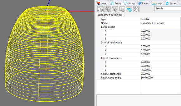
4. Create a Revolved Reflector
Click the Photopia Object Properties icon in the Photopia Settings panel to view the properties for this PODT profile. Change the Type property to Revolve. The reflector does not need to be selected to edit these object properties, but as you add more Photopia objects to your model, such as the lamp, selecting the object will isolate that object’s settings in this panel.
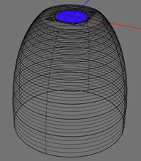
5. Insert the COB LED
Click on the Photopia Lamps panel and type “CXA” into the search box. Click on “CXA3050-5100K” in the list shown, then click the “Add Lamp” button. Move your mouse into the CAD view and press Enter (don't click your mouse). This will insert the lamp model at the default location of 0,0. This aligns the optical center of the lamp model, which is the center of the emission surface, with the focus of the reflector design.
6. Prepare & Run the Photometric Simulation
Select the reflector and click the Photopia Materials panel. Enter “spec 85” into the search box and select “Generic SPEC 85” in the list. Then click the Assign selected material button. Alternatively, you can double click on the material in the list. This material represents an 85% reflective, specular surface, similar to the performance of vacuum metalized aluminum.
Go to the Photopia Settings panel and click the Photometric Output Settings icon.
Set the Horizontal test angles to: 0.
Set the Vertical test angles to: 0(2.5)90.
Set the Photometric Center Point Z value to -90.
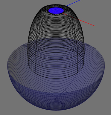
You can click the Show/Hide photometric sphere icon on the Photopia toolbar to confirm the photometric coordinate system is properly oriented and located with respect to your reflector. Click the icon again to toggle this view off.
Click the Start raytrace button.
7. View the Results
Click View Results in the Photopia Toolbar or menu
The Reports Panel has buttons for viewing a few simple reports.
Clicking on the Indoor summary icon will show that this initial reflector produced about a 55° beam angle with the peak off center. Since we were targeting a 40° beam angle with a centered peak, we need to adjust the reflector parameters.
Tip : In Rhino and External Reports
The Reports Panel has buttons for viewing the following:
- Raytrace report
- Intensity plot
- Recording plane report
- Intensity table
- Indoor summary
- Outdoor summary
- Export IES/LDT file
- View results in Photopia Reports
You can view other report types in Photopia Reports, including our full photometric reports, standard reports and additional plot styles.
8. Modifying the Reflector
Select the reflector in the CAD view and then click Design reflector . This will open the PODT view showing all the reflector design parameters. We will modify some of the parameters that will narrow the beam angle and increase the amount of light aimed toward the beam center.
Change the Start angle to 27.5 and click Update Aiming.
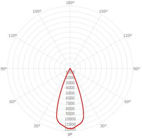
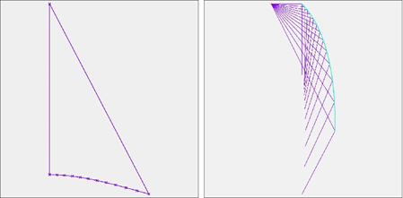
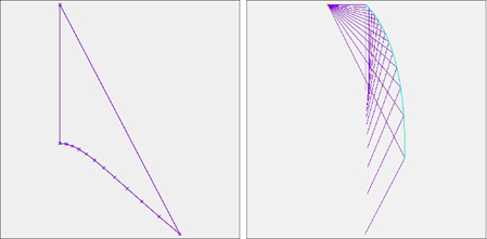
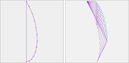
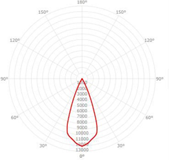
We will change the Weight exponent to -5, but before doing so, first increase it from the default of 1 to 3. As described in the Weighting Factors box to the right, a higher WF exponent directs more light to the wider angles in the beam. You therefore see the reflector sections aimed toward the wider angles increasing in size while the sections aimed toward the central angles decrease in size. Now change the WF exponent to -5. This results in the highest weight at 0°, with WF's tapering at wider beam angles. The next set of images show the WF polar plots along with their associated reflector profile geometry for these WF exponents.
Close the PODT screen and the reflector surface geometry will be updated based on the new parameters.
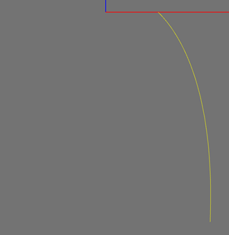
Weighting Factor (WF) polar plot (left) & reflector profile (right) for a WF exponent = 1.
WF exponent = 3
WF exponent = -5
Tip : Weighting Factor Details
The Weighting Factors (WF) determine the relative importance of each reflector aiming section. A higher weight means more of the reflector angular extent will be aimed toward that angle. Increasing the WF exponent creates higher WF's at wider angles in the beam. A negative WF exponent creates higher weights in the beam center, with a stronger emphasis at 0° the more negative the exponent. See the PODT section of the Photopia for Rhino User's Guide under Support on our web page for a more complete explanation of the WF equation.
Weighting Factor Details9. Rerun the Raytrace
Before running the raytrace again, we'll increase the # of rays and add a 5m x 5m recording plane 2.5m below the reflector to view the quality of the light pattern.
Increase the # of rays in the Analysis settings to 5,000,000.
If your reflector was created in the Default layer, then change that layer name to Reflector and give it a color of cyan.
Create a new layer named “Recording planes” with a color of white and make it current. While in the Top view cplane, choose Surface > Plane > Corner to Corner from Rhino’s main menu. Enter -2500,-2500,-2500 for the first corner and @5000,5000 for the second corner.
Select this surface and click Add recording plane .
Give it a name of “P1” and accept the default resolution parameters.
Run the simulation again.
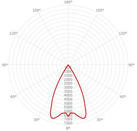
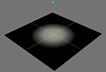
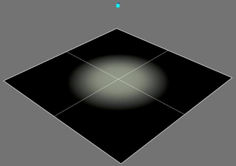
You should now see a beam with the following distribution and about a 40° beam angle.
10. Refine the Beam Profile
While the intensity distribution meets the basic beam angle requirement, it could provide a better looking spot with a smoother taper from the center outward. The bright central spot seen on the recording plane has a relatively abrupt change to the dimmer fringe before tapering off completely. This abrupt transition happens where the intensity distribution plot makes a relative sharp change at around 15°. It's best if the intensity polar plot tapers more smoothly, thus having a more rounded shape. One optical feature that can help smooth the beam from the center outward is discrete facets or steps in the reflector profile.
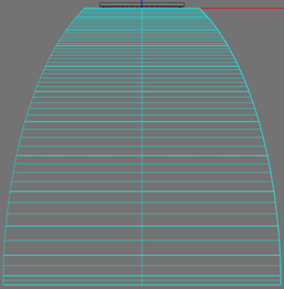
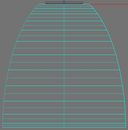
Facets can be added to the reflector profile by changing the Curve resolution in the PODT view. This parameter defines the angular resolution of the polyline profile that approximates the parabolic curves for each aiming section. The default is 1°, meaning a new point along the polyline profile will be used every 1° of angular sweep about the lamp center. Using a larger angle for this resolution results in larger reflector facets, up to a single facet for each aiming section. We'll use a Curve resolution of 10° to see if it helps smooth the spot appearance.
Reflector profile with 1° Curve resolution on the left and 10° on the right. Each reflector aiming section on the right is approximated by a single line segment, thus creating larger facets along the reflector profile.
Run the new simulation with 10,000,000 rays to see a more refined beam pattern. The results below show that the intensity plot is now more rounded and the taper in the spot is smoother. The beam angle increased to about 41.4° since the larger facets also add a bit of beam spread, but this is still close to our desired 40° beam angle.

11. Complete
CONGRATULATIONS! You have completed the PODT reflector design tutorial.
Next Steps
Now that you've designed a reflector, we suggest the following next steps.
- Continue to modify the WF exponent, the range of aiming angles, the curve resolution and even the individual WF adjustments for each reflector section to see the effects these parameters have on the beam performance. The relatively large source size limits your ability for fine control of the beam shape, but these parameters still provide you with the means to modify the beam toward your desired goals.
- Design a new reflector with your own beam requirements.
- Review the general PODT documentation
- Complete more tutorials including those for parametric lens design.