Beginner Tutorial: Analyze a Luminaire
This tutorial will show how to setup a Photopia simulation and view the results inside of Rhino using the Photopia plug-in. The Photopia plug-in requires Rhino 6 or later. The model to be simulated includes an LED collimating lens, a lens holder, the PCB and the geometry for the LED to be used. All geometry is based on surface and polysurface entities in Rhino and the model units are mm. The tutorial provides some extra explanations of many input parameters, which you can skip past if you already have experience with Photopia.
Skill Level
Beginner
Downloads
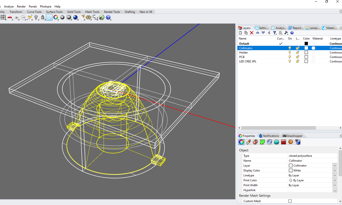
1. Open the Sample Rhino Model
To open this model, choose File > Open and browse to the location where you’ve saved the LED_Collimator.3dm file, which you can download above.
Tip : Setup Rhino First
If you haven't yet installed, setup or licensed Photopia for Rhino, follow the Rhino Setup tutorial first and then come back to this tutorial.
Install, Setup and Licensing Tutorial2. Select the Photopia Lamp Model
Click on the Lamps Panel.
Type "xp-l" in the search box and click the XP-L-3000KCORE model from the filtered list.
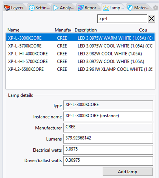
We'll leave all the lamp properties at their defaults.
Click Add Lamp to begin placing the lamp model.
3. Place the Photopia Lamp Model
Press Enter to accept the default location of 0,0,0 at the command prompt.
The lamp will be inserted with the optic center at the origin and the light emission centered around the world -Z axis.
Tip : Locating the Lamp
There are two ways you can place the lamp in the model:
- Drag and drop the lamp into the model by moving and left clicking your mouse.
- Enter the lamp coordinate into the command prompt.
The optic center of an LED model is typically located in the center of the chip emission surface.
4. Assign Acrylic to the TIR Collimator
Select the TIR Collimator geometry in the CAD model.
Click on the Materials Panel. and type "8N" in the Search box to find a typical Acrylic.
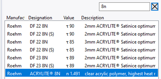
Click on the Roehm ACRYLITE 8N Refractive material.
Tip : Material Assignment
Photopia materials are assigned directly to the CAD geometry. This means you can assign unique materials to each surface, regardless of the layer the item is on.
5. Assign Other Materials
Select the Holder geometry in the CAD model.
In the Materials Panel. search for black
Click on the first G E Plastics Noryl 701 material.
Select the PCB geometry in the CAD model.
In the Materials Panel. search for PCB
Click on the first White PCB material.
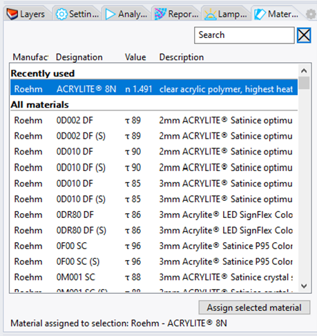
Tip : Recently Used Materials
You can place the Photopia Toolbar in any location. You can also move individual icons around.
At the top of the search results, you'll always see your recently used Materials.
6. Define a Recording (Illuminance) Plane
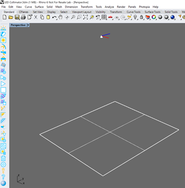
Create a 2m x 2m plane 2m below the optic using the directions in the "Tip" box.
Click Add Recording Plane in the Photopia Toolbar or menu
Type Plane 1 for the plane name and press Enter twice to accept the default numbers of rows and columns.
Tip : Draw your own Recording Plane
Any flat rectangular surface can be made into an illuminance plane.
To add a new 2mx2m plane 2m below the optic, follow these steps:
- Create a new layer named Illuminance Plane.
- Make that layer the Current layer.
- Go to the Top View window.
- Choose Surface / Plane / Corner to Corner from the main menu.
- Type -1000,-1000,-2000 for the first point (lower left corner).
- Type @2000,2000 for the second point (upper right corner).
- Hit Enter to end the command.
Then you can select that new plane and use Photopia's Add Recording Plane to setup this new plane.
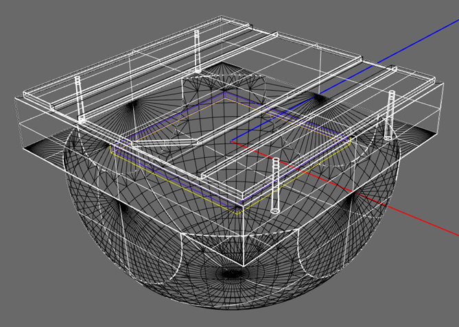
7. Specify Surface Mesh Resolution
The raytrace will be run on meshes that represent the NURBS surfaces used to define the parts of this model.
Click Mesh Parameters in the Photopia Toolbar or menu.
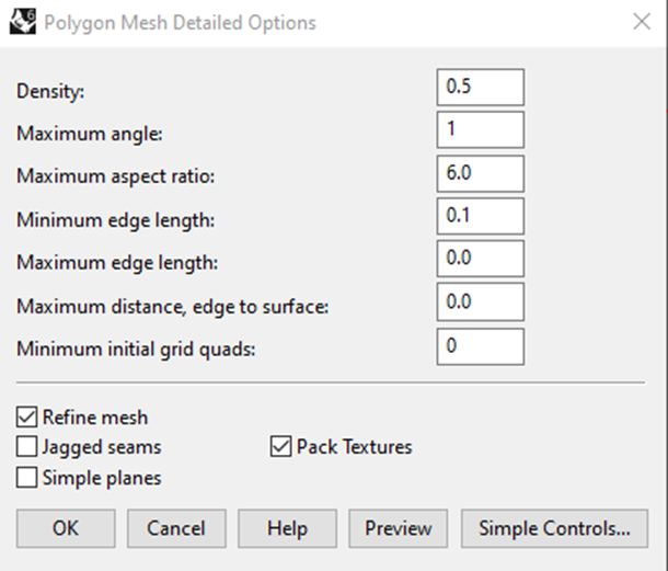
Click Detailed Controls... to open the expanded controls.
Change the Maximum Angle to 1 to specify the maximum angular deviation of the mesh to the NURBS as 1deg.
Click Preview to confirm the settings before clicking OK to accept the settings.
Tip : Mesh Resolution
A '0' value, means that parameter is non-controlling and other parameters take precedence.
These mesh settings apply to all optical geometry except for lamps, as they are based on their own internal meshes.
8. Define Analysis Settings
Click the toolbar button for the Raytrace Settings
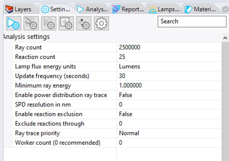
Change the Ray Count to 5,000,000 instead of 2,500,000
Leave all other settings at their defaults.
Tip : Number of Rays
More rays will show more detailed results. Some general guidelines are as follows:
- 250,000 for an accurate efficiency
- 2,500,000 for smooth candela distributions (depending on angular zone sizes)
- >5,000,000 for very smooth recording planes (depending on plane resolution)
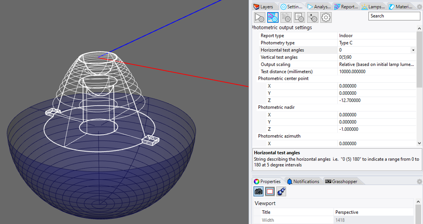
9. Define Photometric Output Settings
Click the toolbar button for the Photometric Output Settings
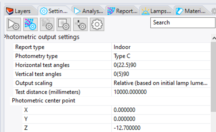
Change the Horizontal Test Angles to 0 instead of 0(22.5)90
Change the Photometric Center to -12.7 Z instead of 0
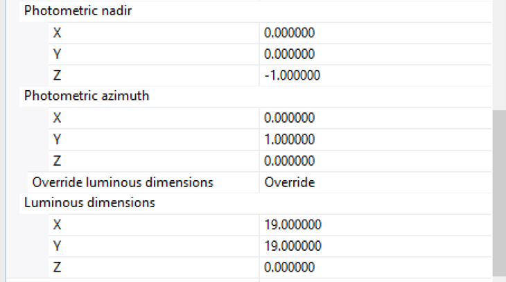
Change the Luminous Dimensions to 19 X, 19 Y, 0 Z instead of 0 X, 0 Y, 0 Z
Leave all other settings at their defaults.
The Why's
Horizontal Test Angles: This is set to 0 since the beam will be axially symmetric.
Photometric Center: This is set to -12.7 so it is in the center of the face of the optic.
Luminous Dimensions: Thare set to represent the emission size of the lens.
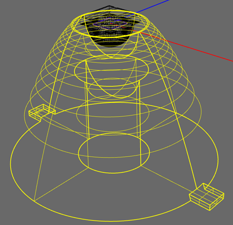
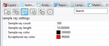
10. Define Sample Rays
Click the toolbar button for Filter 3D Rays
Change the Sample Ray Count to 500 instead of 0
Change the Sample Ray Length to 10 instead of 0
Tip : 3D Rays
Viewing a small set of the 3D rays allows you to get a qualitative view of how the light interacts with the optical components. Viewing 500-2000 rays is typically enough while avoiding too many lines on the screen, but if you will be filtering rays based on other parameters, you may want to display a higher number.
11. Start the Raytrace
Click Start Raytrace in the Photopia Toolbar or menu
The Analysis Status Panel will automatically open so you can follow the raytrace progress.
Tip : Off Layers
Any layer that is off will not be included in the raytrace, even if it has a Photopia property assigned.
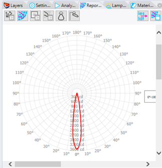
12. View the Results
Click View Results in the Photopia Toolbar or menu
The Reports Panel has buttons for viewing a few simple reports.
Tip : In Rhino and External Reports
The Reports Panel has buttons for viewing the following:
- Raytrace report
- Intensity plot
- Recording plane report
- Intensity table
- Indoor summary
- Outdoor summary
- Export IES/LDT file
- View results in Photopia Reports
You can view other report types in Photopia Reports, including our full photometric reports, standard reports and additional plot styles.
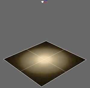
13. View the Results in the CAD Model
Click Show/Hide 3D Rays in the Photopia Toolbar or menu to show the 3D Rays in the CAD model.
Click Show/Hide Recording Plane in the Photopia Toolbar or menu to show the Recording Plane in the CAD model.
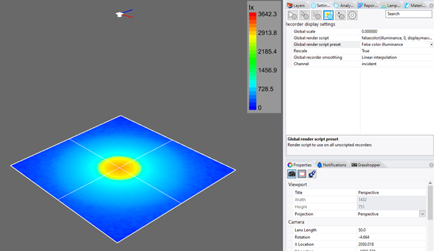
Tip : Recording Plane Settings
In the Settings Panel click on the Recording Plane Settings and you can change the plot display type from TrueColor to False Color. You'll see the plot updated in the CAD view.
Next Steps
Now that you've run your first raytrace, we suggest the following beginner tutorial.