Intermediate Tutorial: Compute Luminance
This tutorial describes how to configure a simulation in SOLIDWORKS to produce a luminous image of an optic. This is done by placing a smooth spherical lens and aperture between the object to be imaged and an illuminance plane (projection plane). The tutorial recommends the lens and aperture parameters that produce a good quality (focused) image.
If you need to review the basics of Photopia for SOLIDWORKS, then start with the SOLIDWORKS Beginner Tutorial.
Skill Level
Intermediate
Downloads
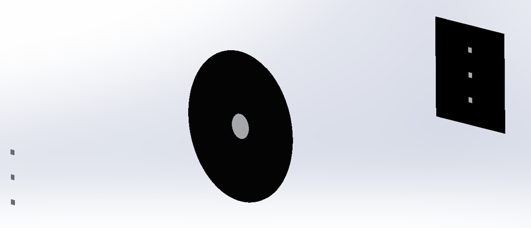
This image shows 3 LEDs on the left that are imaged onto the projection plane on the right.
1. Determine Lens Parameters
Download the Excel Worksheet above and open it.
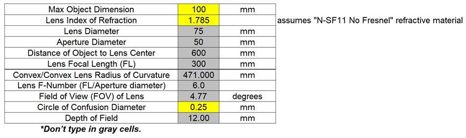
Based on the general guidelines to the right, you'll fill in the spreadsheet to determine the parameters to use for the smooth lens in Step 4.
Lens & Aperture Guidelines
Getting a focused image with the required resolution requires determining the parameters for the projection lens. We have created a spreadsheet, linked above, which helps with determining these parameters.
General Guidelines:
- The imaging lens focal length (FL) should be about 3 times the size of the object to be imaged.
- To produce an image the same size as the object, the distance from object to lens is 2 times the FL and the distance from lens to the imaging plane is also 2 times the FL.
- We recommend an aperture diameter of 1/6 the focal length. The lens F-Number is FL/(aperture diameter), so this is an F6.0 and generally produces a good focus from the single imaging lens.
- The lens diameter should be 1.5 times the aperture diameter.
- The edge thickness at the outer circumference of the lens should be nearly 0 so the 2 spherical surfaces of the convex-convex lens come to a point. This can be achieved by specifying a center lens thickness of 0 in the lens definition. In this case, the lens will be made with the minimum edge thickness around its circumference.
- It's convenient to build the lens in the Right sketch plane in SW if beam is along the Z axis.
- We recommend using the “N-SF11 No Fresnel” refractive lens material since it has special surface properties that remove the Fresnel Reflections and thus create an image free of secondary scattered light effects and keeps the transmittance constant across the entire lens surface, thus reducing vignetting effects.
2. Create Spherical Lens Part
Open SOLIDWORKS and start a new Part document.
Make your part units in Metric (MMGS).
Save the part as “Smooth Lens”.
3. Create Sketch Plane
The lens profile will be created in the current sketch plane.
Open your desired sketch plane.
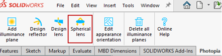
Click the “Spherical lens” icon on the Photopia CommandManager.
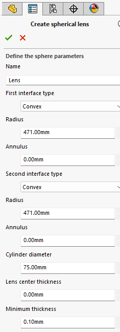
4. Specify Lens Parameters
Name: Lens
Any description for the part.
The following are specified for each side of the lens:
Interface type: Convex
The options are convex, concave of plane. The first interface is drawn on the -X side of the profile in the sketch plane.
Radius: 471mm
If convex or concave is selected, then this specifies the radius of the feature.
Annulus: 0mm
The width of the annulus feature, which is a flat flange around the circumference of the lens.
Cylinder diameter: 75mm
The diameter of the entire lens, including the annulus.
Lens center thickness: 0mm
The center-to-center thickness of the lens, enter 0 for the lens to be constructed as thin as possible.
Minimum thickness: 0.1mm
The minimum thickness of the lens, overrides the Lens center thickness.
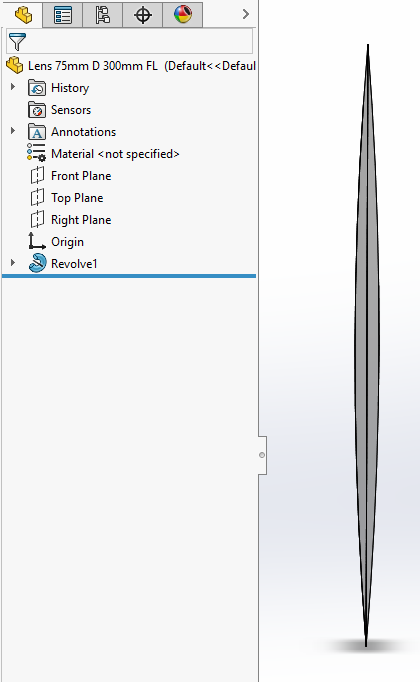
5. Revolve Lens Profile
Click OK ( ✔ ) to create the Smooth Lens, which will insert the Revolve Boss/Base Feature into your part.
Save your part.
6. Create an Aperture Part
An aperture will be used to ensure only light that interacts with the lens hits the projection plane. The aperture hole size is based on the Worksheet in Step 1.
In a new part document, create an aperture, either as a surface or thin solid.
Assign the ZERO0000 reflector material to this part, which has a reflectance of 0%.
Save the aperture part.
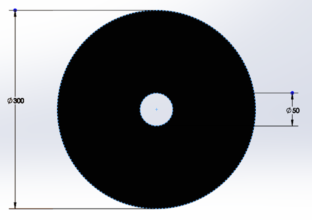
7. Create the Projection Plane Part
You will create an illuminance plane that receives light through the smooth lens and is a projection of the luminous view of your luminaire. The plane size should be large enough to capture the full image of the object being imaged and have a grid resolution based on the level of detail required in the luminous view.
For this example, the plane size is set to be 200mm x 200mm to provide some padding around the object image. This project uses a high grid resolution or 800 x 800, which is a 0.25mm resolution. This high resolution will require more rays to be traced.
For help creating an illuminance plane, you can view step 9 of this tutorial.
Save the projection plane part.
8. Setup the Assembly
Define the location of all the parts according to the advice above. The center of the lens is placed 2 times the FL from the emission surface of the object being imaged. The aperture should be placed just in front of the lens, but not touching the lens. The illuminance plane is placed 4 times the FL from the object emission surface or focal point of the system. Remember that you need to set the location of the illuminance plane surface in the assembly before defining that surface as an illuminance plane in SOLIDWORKS since the Photopia add-in does not maintain a link between that surface and the illuminance plane definition after it is created. If you need to move an illuminance plane or resize the surface, then you need to click the "Delete all illuminance planes" button and redefine them after making the changes to the geometry.
9. Run the raytrace
Projected images require a relatively high number of rays since many of the emitted rays don’t pass through the imaging lens and contribute to the image. It is therefore common to use 100 million rays or more to produce good quality images depending on the model parameters. Because of this, there is an incentive to minimize the model complexity. If you therefore have a model with a repetitive luminous appearance, we recommend modeling only a small section of the overall optic to confirm the luminous qualities of the feature of interest. For example, if evaluating whether individual LEDs are seen through a diffusing lens, then only a small set of the LEDs needs to be simulated rather than all LEDs in the entire device.
10. Convert Illuminance to Luminance
The illuminance plane values are directly proportional to luminance values. They can therefore be converted to luminances with an appropriate scale factor. The scale factor can be determined by simulating a source with a known luminance at a given F-Number. Once the factor is determined for this condition, then it can be scaled to other F-Numbers based on the ratio of lens areas. Using this process, the scale factor for an F6.0 projection system was determined to be 176.6. This factor is luminance/illuminance, so it is used to multiply the illuminance values. If illuminance is in lux, then the luminance will be cd/m2. If illuminance is in footcandles, then luminance will be cd/ft2.
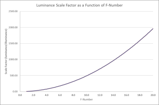
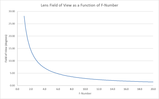
This plot shows how the luminance scale factor values vary as a function of the projection system F-Number. See the spreadsheet for specific values.
Tip : Field of View Average
The luminance values produced with this process will be an average over the field of view (FOV) of the image projection system. The FOV is defined as the full angle subtended by the aperture from the focal point of the object. For an F6.0 system, the FOV is 4.77°, so light is captured by the lens from an angle of about 2.4° above and below the optical axis (center line through the system). This means the luminance values are being averaged over this range of view angles. For evaluating diffusing lens appearances, this is acceptable since the luminance of the lens isn’t likely to significantly change over such a small range of view angles. Other systems that have luminous properties that do change over smaller angular ranges would benefit from a higher F-Number. Otherwise, the computed luminance values will be less accurate.