UVC Disinfection General Information
UVC disinfection applications can generally be evaluated in similar ways that lighting applications are evaluated. The main difference is that the lamp output is quantified in radiant watts in the UVC range rather than lumens. Radiant watts are the portion of electrical watts that are converted into radiant energy by the lamp. For a low pressure mercury (LPM) lamp, this is about 30% of the electrical watts. For UVC LEDs, this is in the range of 1 to 2% of the electrical watts. Lumens are just a subset of the lamp radiant watts, weighted according to their ability to stimulate the human visual system. So lumens are still a metric that quantifies radiant energy, just a specific portion of that radiant energy. All lumen based output is photometric, while radiant watt based output is radiometric.
Skill Level
Beginner
Downloads
none
Units
The main difference is that the lamp output is quantified in radiant watts in the UVC range rather than lumens. Radiant watts are the portion of electrical watts that are converted into radiant energy by the lamp.
Lighting units vs Irradiation units
Illuminance -> Irradiance
Luminous Intensity -> Radiant Intensity
Luminance -> Radiance
Application Software - AGi32, Visual, Dialux
Lighting design software that is normally used to show illuminance values on planes or room surfaces can also be used to show irradiance values by simply entering the luminaire output in radiant watts rather than lumens, assuming you have a luminaire IES file with radiant intensity values for your UVC luminaire. Even if the software doesn’t show units of W/m2, the values would be in W/m2 if the lamp output were specified in radiant watts.
Unit Translation
If your IES file is in Radiant Watts:
- Lumens are actually Radiant Watts
- Footcandles (fc) is actually W/ft2
- Lux (lx) is actually W/m2
Photopia Units
Photopia can also be used to show the irradiance onto any room surface and Photopia does allow the lamp output to be defined in radiant watts. Furthermore, Photopia can produce luminaire IES files based on radiant intensity values since it can model the UVC lamp output and performance within the luminaire optical system. This includes the unique material properties in the UVC spectral range.
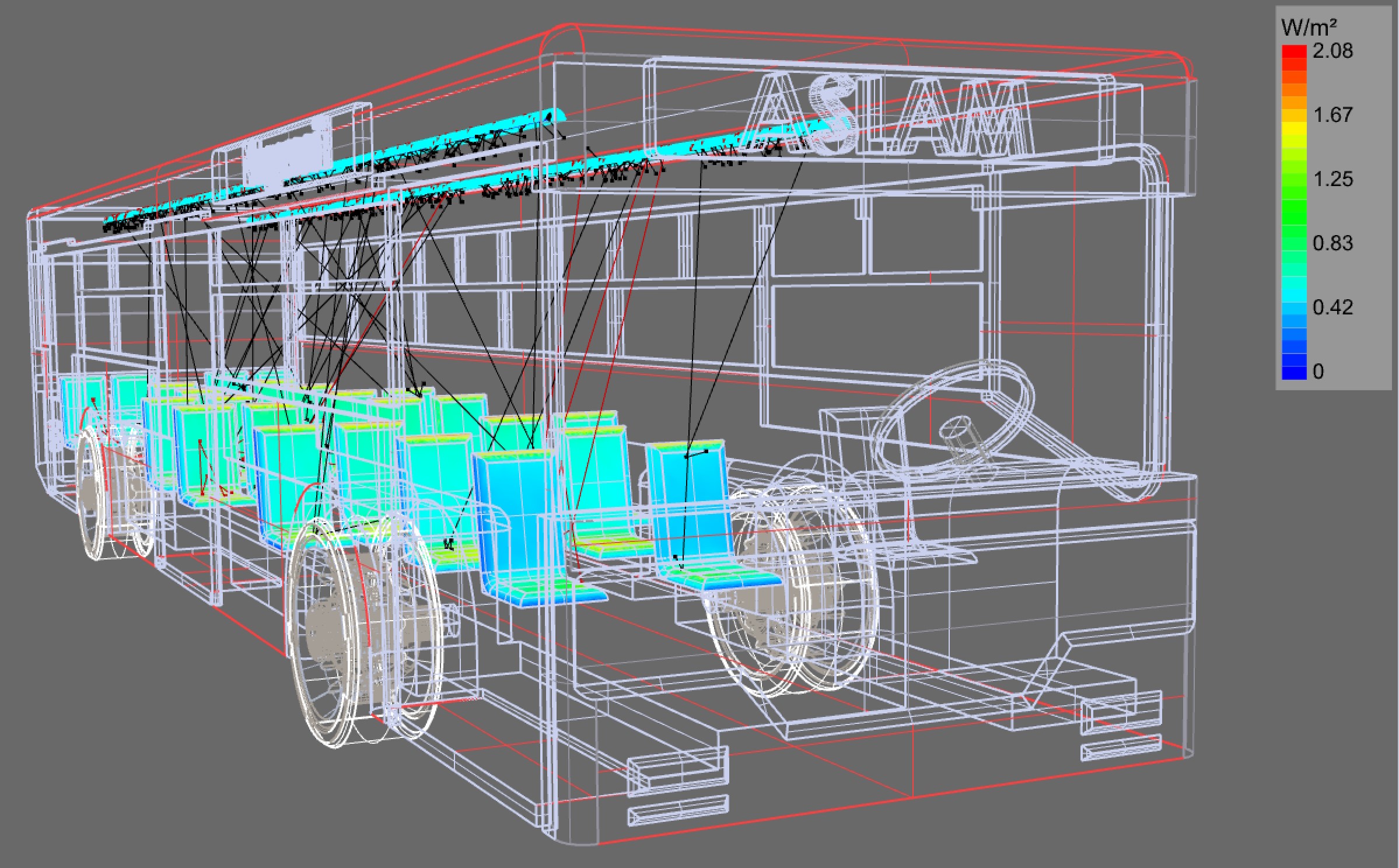
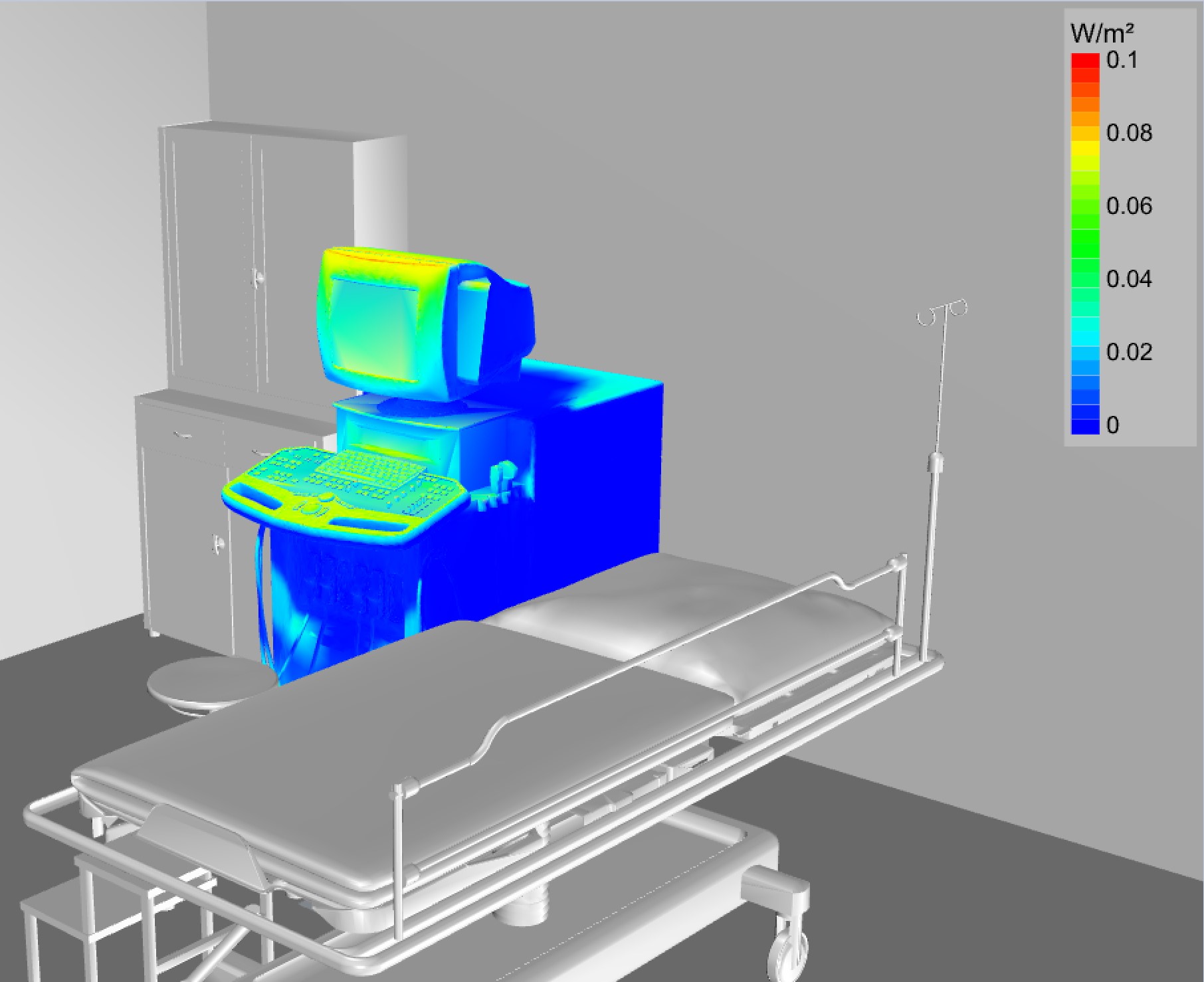
Surface Disinfection - Irradiance
Surface disinfection performance is generally determined by computing the irradiance onto the target surfaces. Irradiance is in units of watts/area. The most common units used for UVC disinfection applications are watts/m2, watts/cm2, milli-watts/cm2 or micro-watts/cm2. Pathogen kill rates are related to the total “dosage” received on the target surface. Dosage is the total energy/area, with the energy units of joules. Since watts are the energy flow rate in joules/second, multiplying watts by the exposure time in seconds results in joules. The typical units for dosage are joules/m2, joules/cm2, milli-joules /cm2 or micro-joules /cm2.
The amount of dosage required for given kill rates such as 90%, 99%, 99.9%, 99.99% depends on the pathogen being eradicated. Furthermore, since standards are still being developed, you will see different dosage requirements for the same pathogens from different references, often resulting from different studies with different test conditions. Therefore for any UVC design, be sure to include the specific reference on which the design is based to support the expected kill rates. For the specific example of deactivating COVID19, the International Ultraviolet Association (IUVA) currently recommends a dosage of 3000 mJ/cm2 for a 99.9% kill rate. You can read more on the IUVA website.
Define Fluence Rate
If you search for the definition of fluence you will find different definitions from different references. The wiki page that mentions it equates it to "radiant exposure," and just relates it to irradiance, watts per surface area integrated over time. That's not the way it is defined by those using it in the UV water treatment and air disinfection industries. A better reference is at the following link. See the definitions for Fluence and Fluence Rate at the top of page 2 in this article.
These confirm the following definitions:
Fluence Rate: Total radiant watts collected onto a spherical surface from any direction, divided by the sphere cross sectional area, not the sphere surface area. The units of fluence rate are watts/area.
Fluence: Fluence is the fluence rate multiplied by time in seconds to get joules/area.
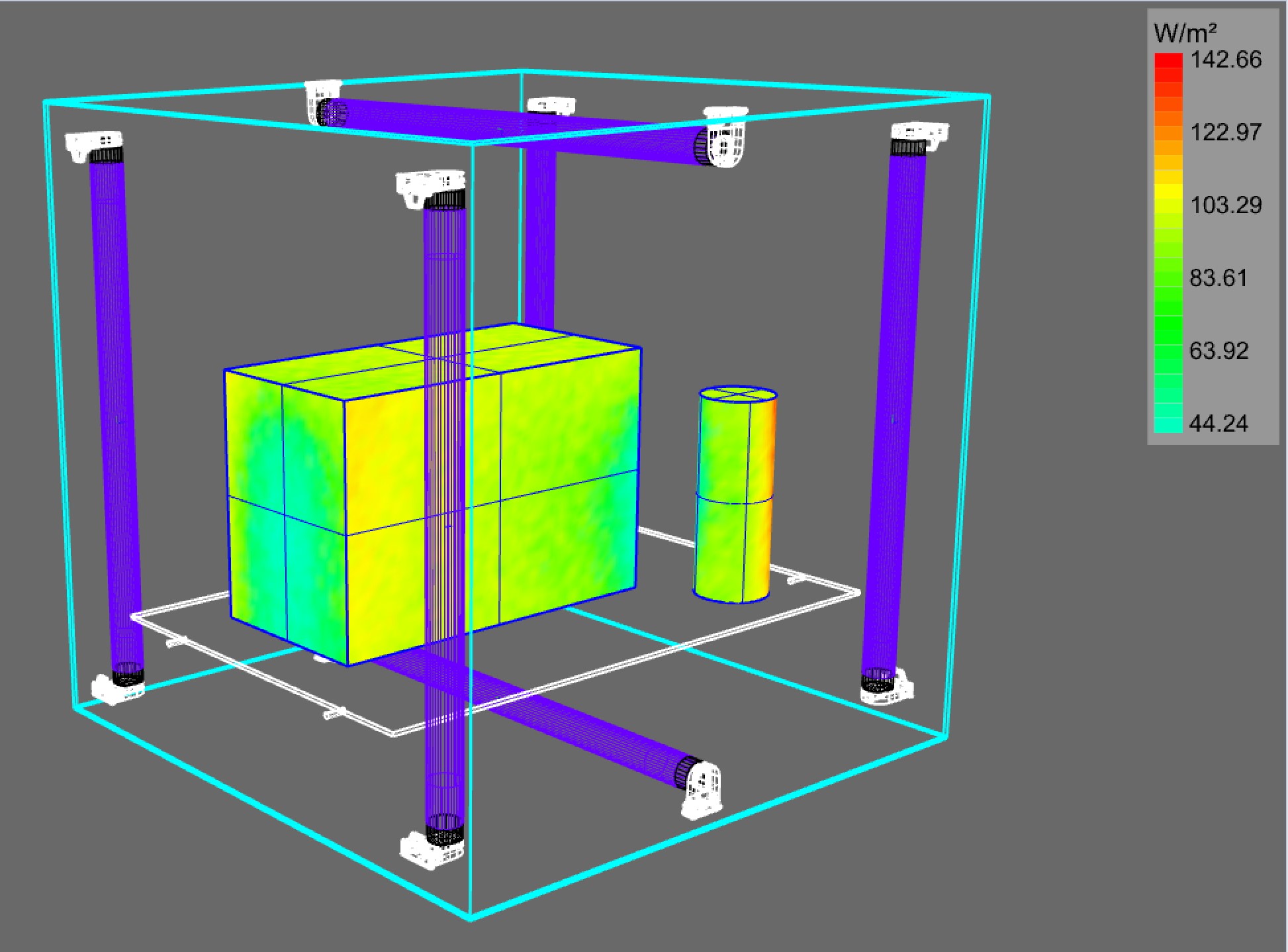
For room air disinfection applications, the most relevant performance metric is fluence rather than surface irradiation. Fluence quantifies the energy onto a particle incident from all directions. It is defined as the total watts onto a sphere from all directions divided by the sphere cross sectional area, not the sphere surface area. It has the same units as irradiance, W/area, but irradiance is the watts/area onto a flat surface and highly dependent upon the incidence angle of the radiant energy.
Upper Air Volume
For upper air volume applications, achieving effective disinfection in the air depends on a lot of factors beyond your luminaire intensity distribution with one of the most important factors being how well the air is mixed. There needs to be active air circulation mechanisms included with the UVC system as well. Assuming well mixed air, the fluence rate values necessary to disinfect vary depending on the references you'll see and the pathogens you want to eradicate. Most that we've seen however, are in the micro-watt/cm2 range. We've seen values as low as 5 micro-watts/cm2, but this reference lists values between 30-50 micro-watts/cm2. Those are probably reasonable values to strive for within a reasonable distance from the luminaires. As mentioned earlier, the energy dosage is what really matters, fluence rather than fluence rate, so the assumption is that the circulating air particles will be within an area receiving these fluence rates long enough to achieve adequate dosages to kill the desired pathogens. When designing a disinfection system, it is best to always include the reference you are using to define your required fluence rate values.
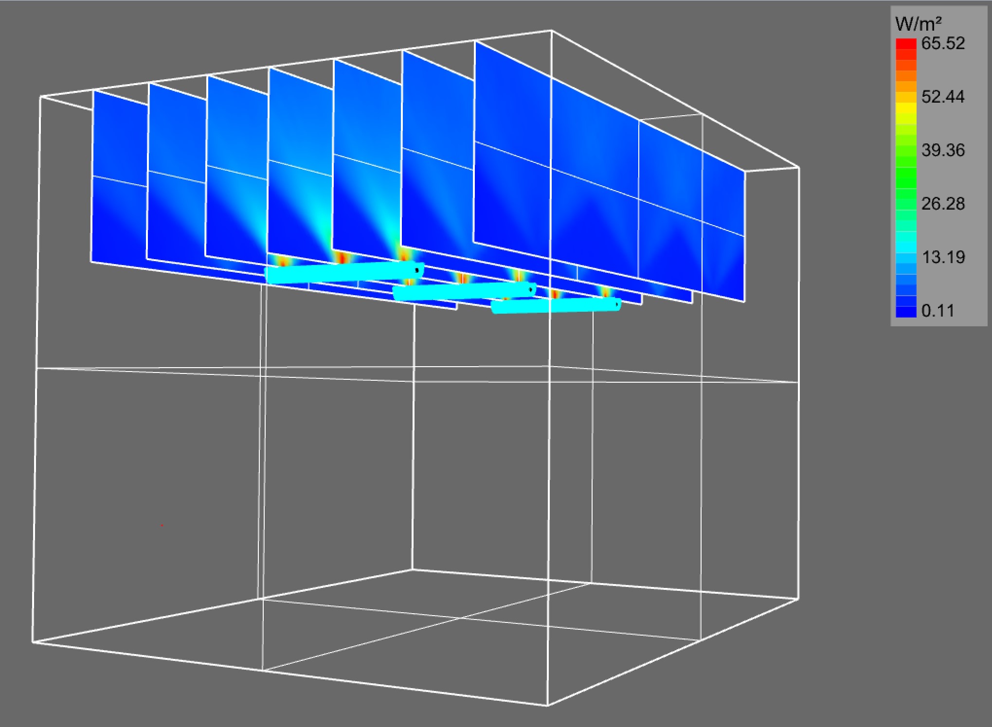
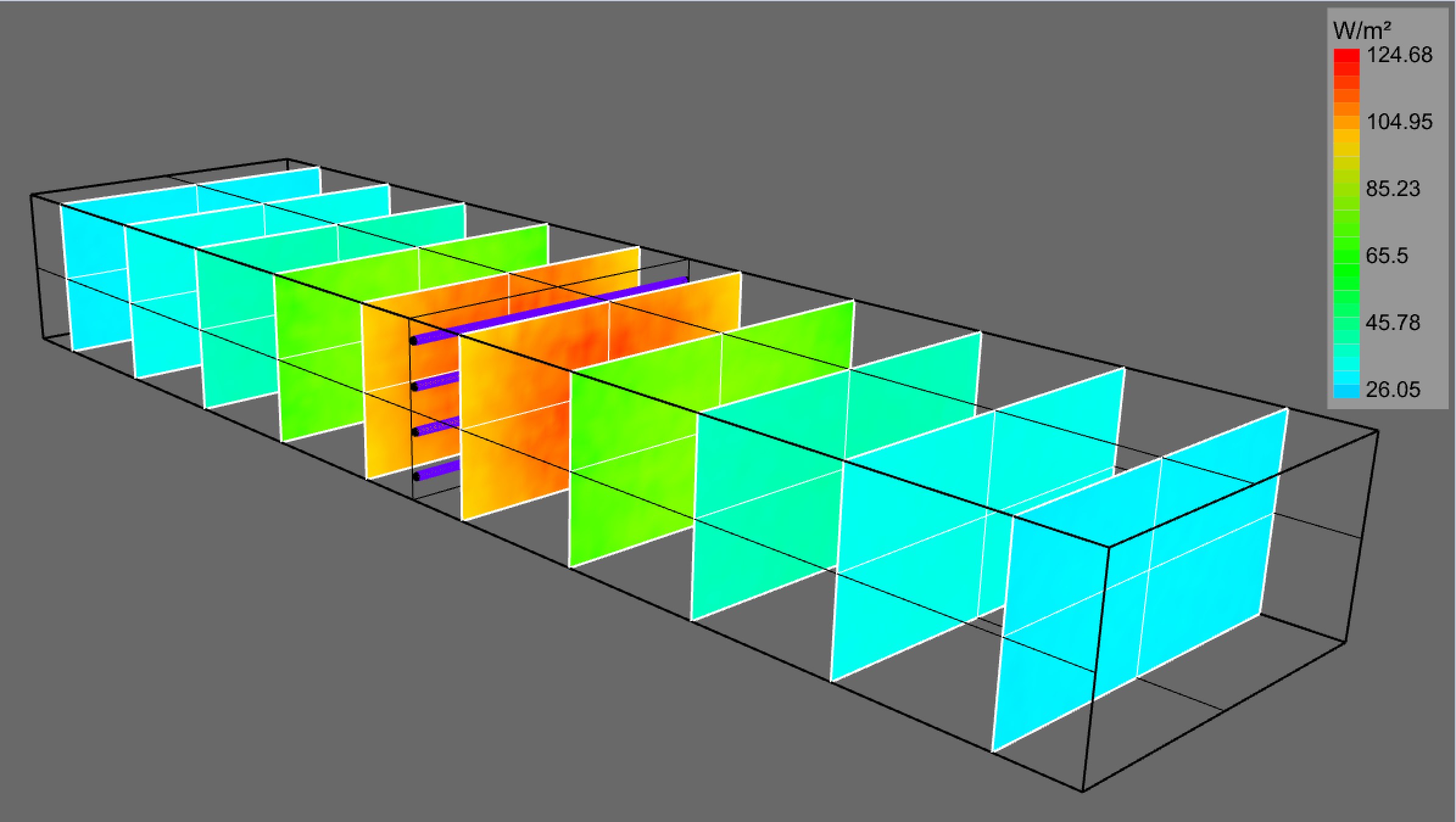
Air Duct Systems
Air duct systems are generally more defined in regards to how long air particles are within the region receiving the UVC energy and therefore allow total dosages/fluence values to be determined. These system are setup with multiple fluence rate grids, each stretching across the air duct and placed at multiple locations before and after the UVC lamp array. The fluence rates are computed on each grid. That set of grids can then be used by a special fluence report that allows the air speed to be entered so the total dosage on air particles traveling through each grid location can be computed over the total length of their path through the system.
UVC In Photopia
In order to get radiometric output from Photopia, you need to set the lamp flux energy units to radiant watts. In standalone Photopia, this is done under Settings / Project Settings. In SOLIDWORKS and Rhino, this is done in the raytrace settings. Once this is done, then illuminance planes become irradiance planes.
The 2021 release of the Photopia for SOLIDWORKS and Rhino both support fluence rate grids. This allows them to be used for air and water disinfection applications. Computing fluence rate values in standalone Photopia requires defining spherical surfaces in the model at locations of interest and manually computing the fluence rate values based on the radiant watt interaction with those spheres.
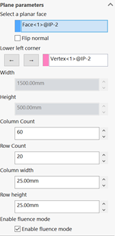
To create a fluence rate grid in SOLIDWORKS or Rhino, start by defining a standard illuminance/irradiance/recording plane. In SOLIDWORKS, there is a checkbox on the plane property management page to indicate fluence rate. In Rhino, you will see a fluence rate checkbox in the object properties panel when you select the plane.
Conversion Factors
Photopia currently provides output in W/m2. You can convert to other units with the following scale factors:
Conversion from W/m2 to mW/cm2: multiply by 0.1
Conversions from W/m2 to µW/cm2: multiply by 100
Conversions from mW/cm2 to µW/cm2: multiply by 1000
Further References
See the following additional resources from various industry organizations for more information on UV disinfection and safety.
CIE UV Documents
The CIE has a range of documents related to using UV energy for disinfection and the safety of such systems. They have released 2 of these documents for free and have others available on their website.
CIE 187:2010 UV-C Photocarcinogenesis Risks from Germicidal Lamps
CIE 155:2003 Ultraviolet Air Disinfection
Read more on the CIE website.
IUVA - International Ultraviolet Association
With a mission of "advancing the sciences, engineering & applications of ultraviolet technologies to enhance the quality of life & protect the environment," the IUVA is a great resource to get involved with if your products are related to using UV energy, especially for disinfection. They have an annual conference, coordinate research, and contribute expertise to standards committees.
In January, Ryan Kelley gave a presentation at a NIST/IUVA conference on "Simulating the Performance of UV Systems", which you can find here.
Read more on the IUVA Website.
IESNA – Illuminating Engineering Society