Intermediate Tutorial: Add a Smooth Lens
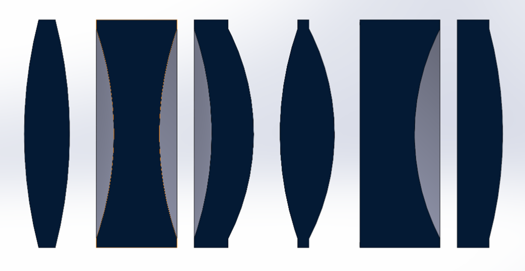
Photopia 2021 for SOLIDWORKS and later supports smooth spherical lens parts. The raytracer will treat the lens geometry as mathematically smooth (not meshed) surfaces. The part definitions support convex, concave and flat surfaces on each side of the lens, as well as annulus features. Spherical lens parts are used for a range of applications including luminous images, lasers, LIDAR, machine vision, and basic imaging analyses. Using mathematically smooth spherical lens part definitions allows Photopia to better support these applications and more.
If you need to review the basics of Photopia for SOLIDWORKS, then start with the SOLIDWORKS Beginner Tutorial.
Skill Level
Intermediate
Downloads
none
1. Initial Part Setup
Open SOLIDWORKS and start a new Part document.
Make your part units in Metric (MMGS).
Save the assembly as “Smooth Lens”.
LIMITATIONS
The lens parts are limited to round/revolved shapes and do not support additional features in the same part file.
Each part file can contain only ONE spherical lens item. Use one part file per lens in your assembly.
2. Create Sketch Plane
The lens profile will be created in the current sketch plane.
Open your desired sketch plane.
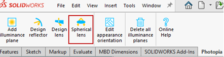
Click the “Spherical lens” icon on the Photopia CommandManager.
Tip : Your own lens CAD model
We cannot convert a cad model of a lens in your model into a smooth lens, you must use our tools to define the lens. You can keep the other lens in the assembly, just don't assign it a Photopia Appearance.
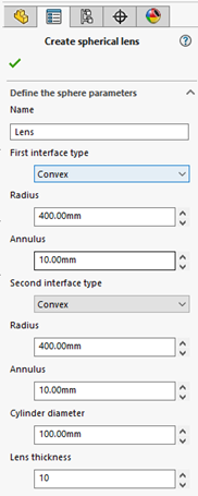
3. Specify Lens Parameters
Name: Lens
Any description for the part.
The following are specified for each side of the lens:
Interface type: Convex
The options are convex, concave of plane. The first interface is drawn on the -X side of the profile in the sketch plane.
Radius: 400mm
If convex or concave is selected, then this specifies the radius of the feature.
Annulus: 10mm
The width of the annulus feature, which is a flat flange around the circumference of the lens.
Cylinder diameter: 100mm
The diameter of the entire lens, including the annulus.
Lens thickness: 10mm
The center-to-center thickness of the lens.
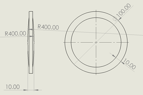
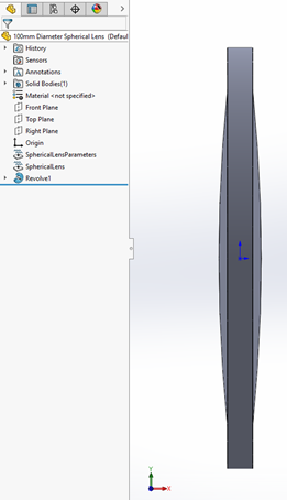
4. Revolve Lens Profile
Click OK ( ✔ ) to create the Smooth Lens, which will insert the Revolve Boss/Base Feature into your part.
Save your part.
5. Edit the Lens
Select the Revolve feature in the FeatureManager.
Click the “Spherical lens” icon on the Photopia CommandManager.
Edit any of your lens parameters.
Click OK ( ✔ ) to update the Smooth Lens.
Save your part.
6. Example Application
You can then place your smooth lens into an assembly, assign a Photopia Appearance to the entire lens part, and run an analysis.
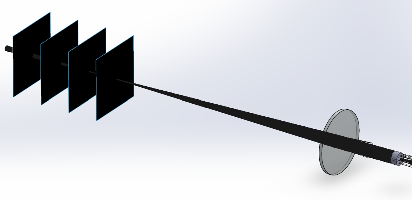
The following images show a 10mm diameter laser directed through a convex-convex lens. The rays are shown to smoothly converge and cross within the set of the irradiance planes.
3D rays from a 10mm diameter laser directed through a smooth spherical convex lens part.
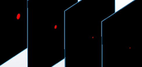
Smooth round spots created on the irradiance planes showing the sizes of the converging and then diverging beam.
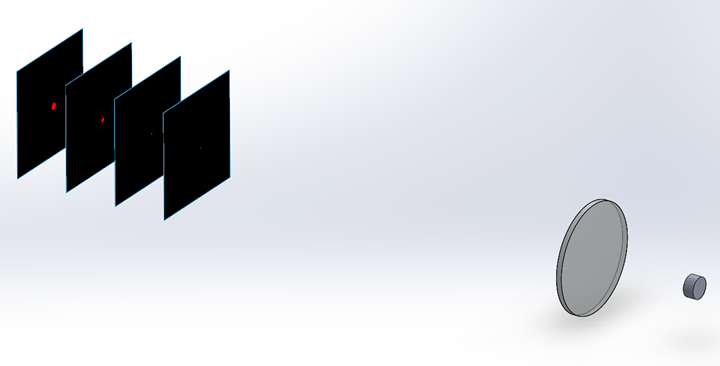
The spots formed on the planes are perfectly round due to the sharp focus of the lens and uniform emission over the laser surface.
Tip : Appearance Assignment
A single Photopia appearance must be assigned to the entire part as Photopia does not support appearance assignment by face on smooth spherical lens parts.
Tip : Mating and Patterns
The parts can be placed within an assembly using standard mates to any of the solid part geometry or reference planes. The lens parts can also be patterned like any other part in an assembly.
LIMITATION : Boolean Operations
You cannot perform any boolean operations on the lens part (union, intersection, holes, trims). It must remain a solid revolve feature.